FRONT AXLE HUB > INSTALLATION |
| 1. INSTALL FRONT AXLE HUB BEARING |
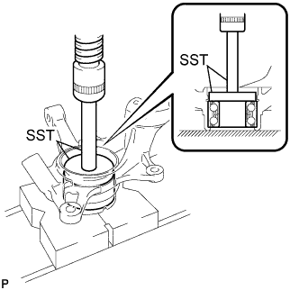 |
Using SST and a press, install a new front axle hub bearing to the steering knuckle.
| 2. INSTALL FRONT LOWER BALL JOINT ASSEMBLY |
Install the front lower ball joint to the steering knuckle with the nut.
Install a new cotter pin.
| 3. INSTALL FRONT DISC BRAKE DUST COVER |
Install the disc brake dust cover to the steering knuckle with the 4 bolts.
| 4. INSTALL FRONT AXLE HUB SUB-ASSEMBLY |
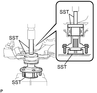 |
Using SST and a press, install the front axle hub sub-assembly.
| 5. INSTALL FRONT AXLE HUB HOLE SNAP RING |
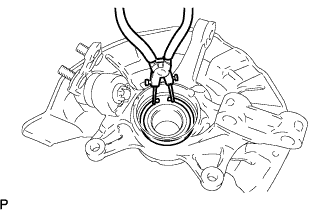 |
Using snap ring pliers, install a new front axle hub hole snap ring.
| 6. INSTALL FRONT WHEEL BEARING DUST DEFLECTOR NO.1 |
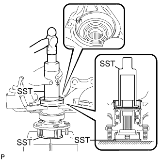 |
Using SST and a hammer, install the bearing dust deflector No.1.
| 7. INSTALL FRONT AXLE ASSEMBLY |
Install the front axle assembly to the front drive shaft assembly.
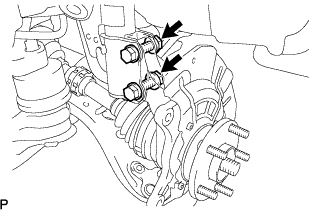 |
Install the front axle assembly to the front shock absorber assembly with the 2 bolts and nuts.
| 8. CONNECT FRONT SUSPENSION ARM SUB-ASSEMBLY LOWER NO.1 |
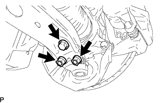 |
Install the lower ball joint to the front suspension arm sub-assembly lower with the bolt and 2 nuts.
| 9. CONNECT TIE ROD ASSEMBLY |
Install the tie rod end to the steering knuckle with the nut.
Install a new cotter pin.
| 10. INSTALL FRONT DISC |
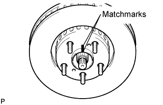 |
Align the matchmarks and install the front disc.
| 11. INSTALL FRONT DISC BRAKE CALIPER ASSEMBLY |
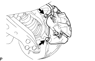 |
Install the front disc brake caliper assembly with the 2 bolts to the steering knuckle.
| 12. INSTALL FRONT SPEED SENSOR |
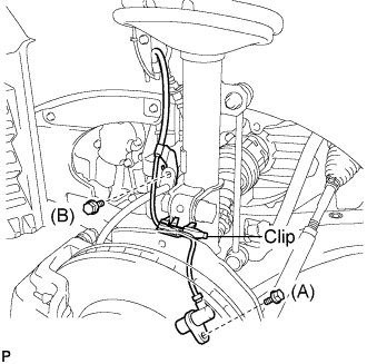 |
Install the speed sensor to the steering knuckle with the bolt.
Install the flexible hose and the speed sensor to the shock absorber with the bolt and set the clip of sensor on the knuckle.
| 13. INSTALL FRONT AXLE HUB NUT |
Using a socket wrench (30 mm), install a new axle hub nut.
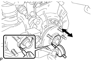
| 14. SEPARATE FRONT DISC BRAKE CALIPER ASSEMBLY |
|
Remove the 2 bolts, and separate the front disc brake caliper assembly.
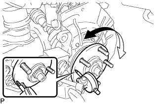
| 15. REMOVE FRONT DISC |
|
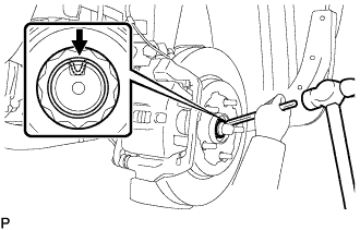
| 16. INSPECT FRONT AXLE HUB BEARING LOOSENESS |
 |
Using a dial indicator, check for looseness near the center of the axle hub.
| 17. INSPECT FRONT AXLE HUB RUNOUT |
 |
Using a dial indicator, check for runout on the surface of the axle hub outside the hub bolt.
| 18. INSTALL FRONT DISC |
|
Align the matchmarks and install the front disc.
| 19. INSTALL FRONT DISC BRAKE CALIPER ASSEMBLY |
|
Install the front disc brake caliper assembly with the 2 bolts to the steering knuckle.
| 20. INSTALL FRONT AXLE HUB NUT |
 |
Using a chisel and hammer, stake the axle hub nut.
| 21. INSTALL FRONT WHEEL |
| 22. ADJUST FRONT WHEEL ALIGNMENT |
| 23. CHECK SPEED SENSOR SIGNAL |
