BRAKE PEDAL > INSTALLATION |
| 1. INSTALL BRAKE PEDAL ASSEMBLY |
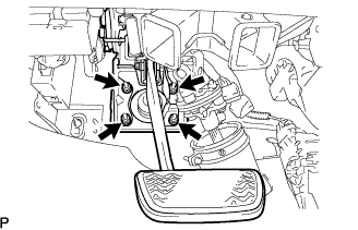 |
Install the brake pedal assembly with the 4 nuts.
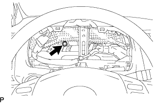 |
Install the brake pedal assembly with the bolt.
Connect the stop light switch connector and pedal stroke sensor connector.
| 2. INSTALL MASTER CYLINDER PUSH ROD CLEVIS |
Apply lithium soap base glycol grease to the clevis pin.
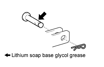 |
Install the clevis pin and a new clip.
| 3. INSTALL BRAKE PEDAL RETURN SPRING |
| 4. INSTALL COMBINATION METER ASSEMBLY |
| 5. INSTALL INSTRUMENT CLUSTER FINISH PANEL SUB-ASSEMBLY |
| 6. CONNECT CABLE TO BATTERY NEGATIVE TERMINAL |
| 7. CHECK AND ADJUST BRAKE PEDAL HEIGHT |
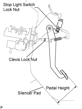 |
Check the brake pedal height.
Adjust the brake pedal height.
Disconnect the connector from the stop light switch assembly.
Loosen the stop light switch lock nut. Turn the switch in order to give the pedal some free play.
Loosen the clevis lock nut.
Adjust the pedal height by turning the pedal push rod.
Tighten the clevis lock nut.
Turn the stop light switch assembly so that the clearance between the nut end and the stop light switch cushion is between 0.5 and 2.4 mm (0.020 to 0.095 in.). Tighten the lock nut.
Connect the connector to the stop light switch assembly.
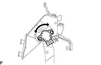
| 8. ADJUST BRAKE PEDAL STROKE SENSOR ASSEMBLY |
 |
Connect the intelligent tester to the DLC3.
Loosen the 2 bolts.
Turn the ignition switch to the ON position. Reading the stroke sensor 1 value shown on the intelligent tester screen, turn the stroke sensor slowly to the right and left to adjust it to the standard voltage.
Tighten the 2 bolts.
Perform system initialization. (Click here)
| 9. CHECK PEDAL FREE PLAY |
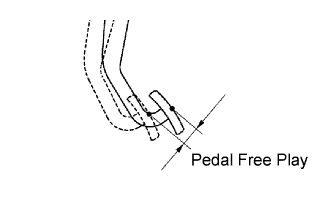 |
Press the pedal until a slight resistance is felt. Measure the distance as shown in the illustration.
If the pedal free play is 1.0 mm (0.039 in.) or less, check the protrusion of the stop light switch assembly shaft.
| 10. CHECK PEDAL RESERVE DISTANCE |
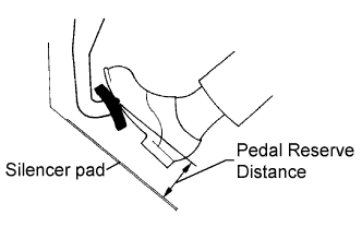 |
Release the parking brake pedal.
With the engine running, depress the pedal and measure the pedal reserve distance as shown in the illustration.
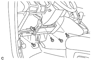
| 11. INSTALL DRIVER SIDE KNEE AIRBAG ASSEMBLY |
Install the driver side knee airbag assembly with the 4 bolts.
 |
Connect the connector to the driver side knee airbag assembly.
| 12. INSTALL INSTRUMENT PANEL FINISH PANEL SUB-ASSEMBLY LOWER |
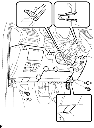 |
Connect the connectors.
Engage the 5 claws and the 4 clips.
Connect the hood lock control cable assembly.
Install the bolt <A>, the screw <C>, and the instrument panel finish panel sub-assembly lower.
| 13. INSTALL FRONT DOOR SCUFF PLATE LH (LHD) |
| 14. INSTALL FRONT DOOR SCUFF PLATE RH (RHD) |
| 15. INSTALL COWL SIDE TRIM ASSEMBLY LH (LHD) |
| 16. INSTALL COWL SIDE TRIM ASSEMBLY RH (RHD) |
| 17. INSPECT SRS WARNING LIGHT |
| 18. PERFORM INITIALIZATION |
