DTC P0560 System Voltage |
| DTC No. | DTC Detection Condition | Trouble Area |
| P0560 | Open in ECM back-up power source circuit (1 trip detection logic) |
|
| 1.CHECK FUSE (IGCT NO.5 FUSE) |
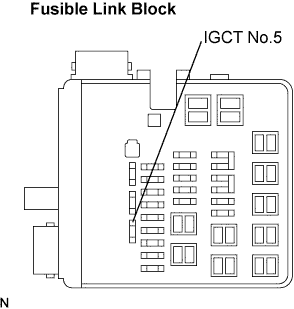 |
Remove the IGCT No.5 fuse from the fusible link block.
Measure the resistance.
Reinstall the IGCT No.5 fuse.
|
| ||||
| OK | |
| 2.INSPECT HV CONTROL ECU (BATT VOLTAGE) |
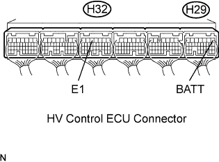 |
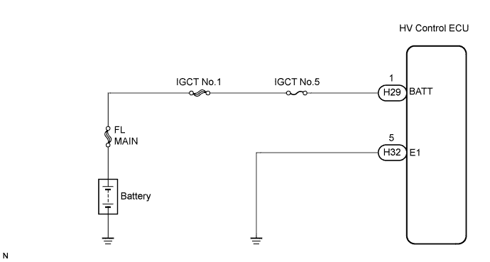
Measure the voltage between the terminals of the H29 and H32 HV Control ECU connectors.
| Tester Connection | Specified Condition |
| BATT (H29-1) - E1 (H32-5) | 9 to 14 V |
|
| ||||
| OK | ||
| ||
| 3.CHECK HARNESS AND CONNECTOR (HV CONTROL ECU - IGCT NO.5 FUSE, IGCT NO.5 FUSE - BATTERY) |
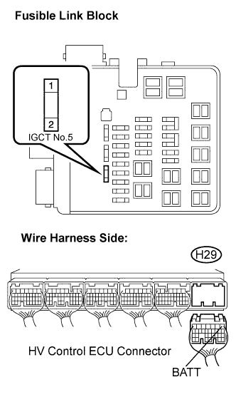 |
Check the harness and the connector between the IGCT No.5 fuse and HV Control ECU.
Remove the IGCT No.5 fuse from the fusible link block.
Disconnect the H29 HV Control ECU connector.
Measure the resistance.
| Tester Connection | Specified Condition |
| IGCT No.5 fuse (2) - BATT (H29-1) | Below 1 Ω |
| Tester Connection | Specified Condition |
| IGCT No.5 fuse (2) or BATT (H29-1) - Body ground | 10 kΩ or higher |
Reconnect the HV Control ECU connector.
Reinstall the IGCT No.5 fuse.
Check the harness and the connector between the IGCT No.5 fuse and battery.
Remove the IGCT No.5 fuse from the fusible link block.
Disconnect the positive battery terminal.
Measure the resistance.
| Tester Connection | Specified Condition |
| Battery positive terminal - IGCT No.5 fuse (1) | Below 1 Ω |
| Tester Connection | Specified Condition |
| Battery positive terminal or IGCT No.5 fuse (1) - Body ground | 10 kΩ or higher |
Reconnect the positive battery terminal.
Reinstall the IGCT No.5 fuse.
|
| ||||
| OK | |
| 4.INSPECT BATTERY |
Check that the battery is not depleted.
|
| ||||
| OK | ||
| ||
