DTC P0100 Mass or Volume Air Flow Circuit |
DTC P0102 Mass or Volume Air Flow Circuit Low Input |
DTC P0103 Mass or Volume Air Flow Circuit High Input |
| DTC No. | DTC Detection Condition | Trouble Area |
| P0100 | Open or short in Mass Air Flow (MAF) meter circuit for 3 seconds |
|
| P0102 | Open in Mass Air Flow (MAF) meter circuit for 3 seconds |
|
| P0103 | Short in Mass Air Flow (MAF) meter circuit for 3 seconds |
|
| Mass Air Flow Rate (gm/s) | Malfunctions |
| Approximately 0.0 |
|
| 271.0 or more |
|
| 1.READ VALUE USING INTELLIGENT TESTER (MASS AIR FLOW RATE) |
Connect the intelligent tester to the DLC3.
Put the engine in inspection mode (Click here).
Start the engine.
Turn the tester ON.
Enter the following menus: Powertrain / Engine / Data List / MAF.
Read the values displayed on the tester.
| Mass Air Flow Rate (gm/s) | Proceed to |
| 0.0 | A |
| 271.0 or more | B |
| Between 1.0 and 270.0 (*1) | C |
|
| ||||
|
| ||||
| A | |
| 2.INSPECT MASS AIR FLOW METER (POWER SOURCE VOLTAGE) |
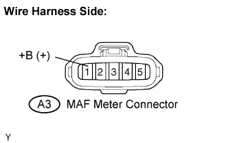 |
Disconnect the A3 Mass Air Flow (MAF) meter connector.
Turn the ignition switch ON.
Measure the voltage between the terminals of the wire harness side connector and body ground.
| Tester Connection | Specified Condition |
| +B (A3-1) - Body ground | 9 to 14 V |
Reconnect the MAF meter connector.
|
| ||||
| OK | |
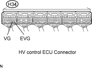
| 3.INSPECT HV CONTROL ECU (VG VOLTAGE) |
 |
Put the engine in inspection mode (Click here).
Start the engine.
Measure the voltage between the terminals VG and EVG of the H34 HV Control ECU connector.
| Tester Connection | Condition | Specified Condition |
| VG (H34-30) - EVG (H34-29) | Engine idling | 0.5 to 3.0 V |
|
| ||||
| NG | |
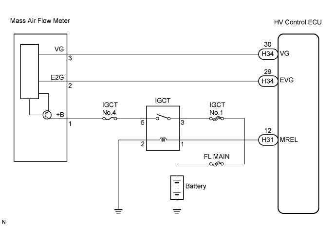
| 4.CHECK HARNESS AND CONNECTOR (MASS AIR FLOW METER - HV CONTROL ECU) |
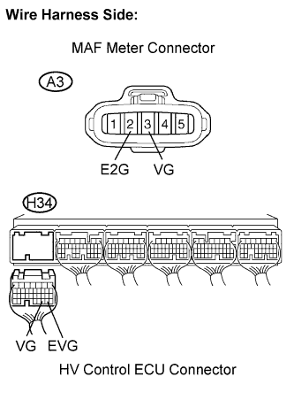 |
Disconnect the A3 MAF meter connector.
Disconnect the H34 HV Control ECU connector.
Measure the resistance between the terminals of the MAF meter connector and HV Control ECU.
| Tester Connection | Specified Condition |
| VG (A3-3) - VG (H34-30) | Below 1 Ω |
| E2G (A3-2) - EVG (H34-29) | Below 1 Ω |
| Tester Connection | Specified Condition |
| VG(A3-3) or VG (H34-30) - Body ground | 10 kΩ or higher |
Reconnect the MAF meter connector.
Reconnect the HV Control ECU connector.
|
| ||||
| OK | ||
| ||
| 5.CHECK HARNESS AND CONNECTOR (MASS AIR FLOW METER - IGCT NO.4 FUSE) |
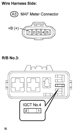 |
Inspect the IGCT No.4 fuse.
Remove the IGCT No.4 fuse from the R/B No.3.
Check the IGCT No.4 fuse resistance.
Reinstall the IGCT No.4 fuse.
Disconnect the A3 MAF meter connector.
Remove the integration relay from the R/B No.3.
Measure the resistance between terminal of the MAF meter and IGCT No.4 fuse.
| Tester Connection | Specified Condition |
| +B (A3-1) - IGCT No.4 fuse (2) | Below 1 Ω |
| Tester Connection | Specified Condition |
| +B (A3-1) or IGCT No.4 fuse (2) - Body ground | 10 kΩ or higher |
Reconnect the MAF meter connector.
Reinstall the integration relay.
|
| ||||
| OK | ||
| ||
| 6.INSPECT HV CONTROL ECU (SENSOR GROUND) |
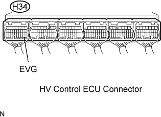 |
Measure the resistance between terminals of the EVG and body ground.
| Tester Connection | Specified Condition |
| EVG (H34-29) - Body ground | Below 1 Ω |
|
| ||||
| OK | |
| 7.CHECK HARNESS AND CONNECTOR (MASS AIR FLOW METER - HV CONTROL ECU) |
|
Disconnect the A3 MAF meter connector.
Disconnect the H34 HV Control ECU connector.
Measure the resistance between terminals of the MAF meter and HV Control ECU.
| Tester Connection | Specified Condition |
| VG (A3-3) - VG (H34-30) | Below 1 Ω |
| E2G (A3-2) - EVG (H34-29) | Below 1 Ω |
| Tester Connection | Specified Condition |
| VG (A3-3) or VG (H34-30) - Body ground | 10 kΩ or higher |
Reconnect the MAF meter connector.
Reconnect the HV Control ECU connector.
|
| ||||
| OK | ||
| ||
