CENTER AIRBAG SENSOR ASSEMBLY > INSTALLATION |
| 1. INSTALL CENTER AIRBAG SENSOR ASSEMBLY |
Check that the ignition switch is off.
Check that the battery negative (-) terminal is disconnected.
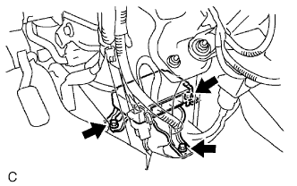 |
Temporarily install the center airbag sensor assembly with the 3 bolts.
Tighten the 3 bolts to the specified torque.
Check that there is no looseness in the installation parts of the center airbag sensor assembly.
Connect the 3 connectors to the center airbag sensor assembly.
Check that the waterproof sheet is properly set.
| 2. INSTALL AIR DUCT REAR NO.1 |
| 3. INSTALL AIR DUCT REAR NO.2 |
| 4. INSTALL CONSOLE COVER LOWER |
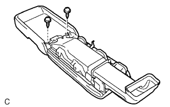 |
Connect the connector to the console cover lower.
Install the console cover lower with the 2 screws.
| 5. INSTALL CONSOLE BOX NO.1 DUCT |
| 6. INSTALL REAR CONSOLE BOX |
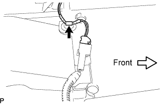 |
Connect each of the clamp and the connector.
 |
Keeping the rear console box pulled in the rear direction of the vehicle, install the 6 bolts from the left and right sides.
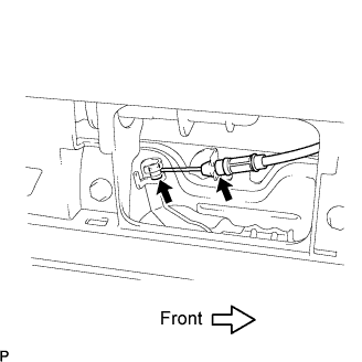 |
Connect the console box lock control cable assembly and install the rear console box.
| 7. INSTALL CONSOLE BOX HOLE COVER |
 |
Slide the front seat assemblies RH and LH forward.
Slide the rear console box fully to the back end and install the console box hole cover.
| 8. INSTALL CONSOLE BOX NO.2 HOLE COVER |
| 9. INSTALL INSTRUMENT PANEL FINISH PANEL LOWER CENTER |
 |
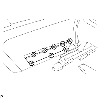
Engage the 2 clips.
Install the 7 screws <C> and the instrument panel finish panel lower center.
| 10. INSTALL FLOOR CARPET COVER CENTER LH |
 |
Slide the floor carpet cover center LH to the rear of the vehicle, and engage the 2 claws to the instrument panel finish panel lower center at the floor carpet cover center LH.
Install the 2 clips and the floor carpet cover center LH.
| 11. INSTALL FLOOR CARPET COVER CENTER RH |
| 12. INSTALL GLOVE COMPARTMENT DOOR ASSEMBLY |
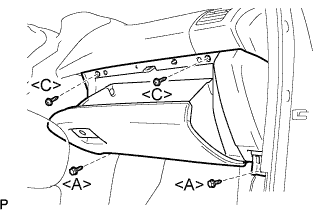 |
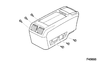
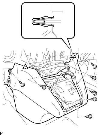
Connect the connectors.
Install the 2 bolts <A>, the 2 screws <C>, and the glove compartment door assembly.
| 13. INSTALL INSTRUMENT PANEL NO.2 UNDER COVER SUB-ASSEMBLY |
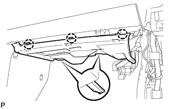 |
Connect the connectors.
Engage the 3 claws and install the instrument panel No.2 under cover sub-assembly.
| 14. INSTALL COWL SIDE TRIM SUB-ASSEMBLY RH |
| 15. INSTALL FRONT DOOR OPENING TRIM RH WEATHERSTRIP |
| 16. INSTALL FRONT DOOR SCUFF LH PLATE |
 |
Connect the connector. (w/ illumination scuff plate)
Engage the 6 claws and 4 clips, and install the front door scuff plate.
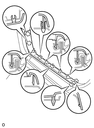
| 17. INSTALL INSTRUMENT PANEL FINISH PANEL SUB-ASSEMBLY LOWER |
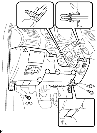 |
Connect the connectors.
Engage the 5 claws and the 4 clips.
Connect the hood lock control cable assembly.
Install the bolt <A>, the screw <C>, and the instrument panel finish panel sub-assembly lower.
| 18. INSTALL FRONT DOOR SCUFF RH PLATE |
| 19. INSTALL INSTRUMENT PANEL FINISH PANEL LOWER |
 |
Connect the connectors.
Engage the 2 clips and install the instrument panel finish panel lower.
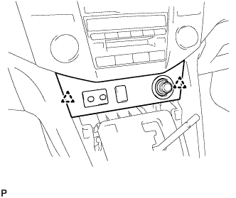
| 20. INSTALL CONSOLE PANEL UPPER FRONT |
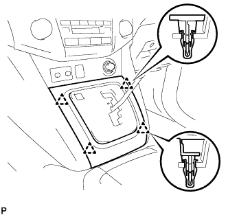 |
Engage the 4 clips and install the console panel upper front.
| 21. INSTALL FRONT SEAT ASSEMBLY |
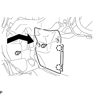
Place the front seat assembly in the vehicle and align the adjuster pin with the hole on the vehicle side.
Connect the connector.
Install the clamp.
Connect the negative battery cable.
Move the front seat assembly to the rearmost position by operating the slide and vertical power seat switch knob.
Temporarily install the front side of the front seat assembly with the 2 bolts.
Move the front seat assembly fully forward by operating the slide and vertical power seat switch knob.
Temporarily install the rear side of the front seat assembly with the 2 bolts.
Move the front seat assembly to the rearmost position by operating the slide and vertical power seat switch knob.
Fully tighten the 2 bolts on the front side of the front seat assembly in the order of the inner side bolt and then the outer side bolt.
Move the front seat assembly fully forward by operating the slide and vertical power seat switch knob.
Fully tighten the 2 bolts on the rear side of the front seat assembly in the order of the inner side bolt and then the outer side bolt.
| 22. CONNECT CABLE TO NEGATIVE BATTERY TERMINAL |
| 23. PERFORM INITIALIZATION |
Perform initialization (Click here).
| 24. INSPECT CHECK POWER SEAT FUNCTION |
| 25. INSPECT SEAT HEATER OPERATION |
| 26. INSPECT SRS WARNING LIGHT |
Inspect the SRS warning light (Click here).
