REPAIR INSTRUCTION > PRECAUTION |
| 1.BASIC REPAIR HINT |
HINTS ON OPERATIONS
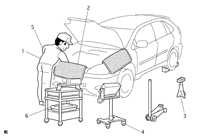
| 1 | Attire |
|
| 2 | Vehicle protection | Prepare a grille cover, fender cover, seat cover and floor mat before starting the operation. |
| 3 | Safety operation |
|
| 4 | Preparation of tools and measuring gauge | Before starting operation, prepare a tool stand, SST, gauge, oil and parts for replacement. |
| 5 | Removal and installation, disassembly and assembly operations |
|
| 6 | Removed parts |
|
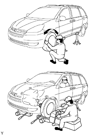
JACKING UP AND SUPPORTING VEHICLE
Care must be taken when jacking up and supporting the vehicle. Be sure to lift and support the vehicle at the proper locations.
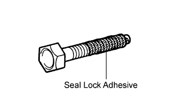 |
PRECOATED PARTS
Precoated parts are bolts and nuts that are coated with a seal lock adhesive at the factory.
If a precoated part is retightened, loosened or moved in any way, it must be recoated with the specified adhesive.
When reusing a precoated part, clean off the old adhesive and dry the part with compressed air. Then apply new seal lock adhesive appropriate to that part.
Some seal lock agents harden slowly. You may have to wait for the seal lock adhesive to harden.
GASKETS
When necessary, use a sealer on gaskets to prevent leaks.
BOLTS, NUTS AND SCREWS
Carefully follow all the specifications for tightening torques. Always use a torque wrench.
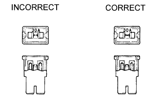 |
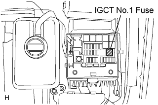
FUSES
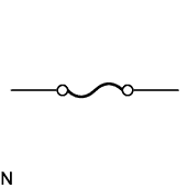
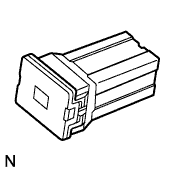
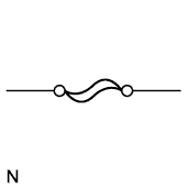
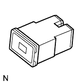
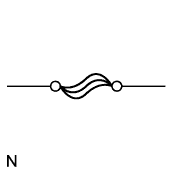
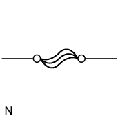
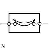
When inspecting a fuse, check that the wire of the fuse is not broken.
When replacing fuses, be sure that the new fuse has the correct amperage rating. Do not exceed the rating or use one with a lower rating.
| Illustration | Symbol | Part Name | Abbreviation |
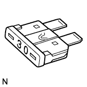 |  | FUSE | FUSE |
 |  | MEDIUM CURRENT FUSE | M-FUSE |
 |  | HIGH CURRENT FUSE | H-FUSE |
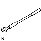 |  | FUSIBLE LINK | FL |
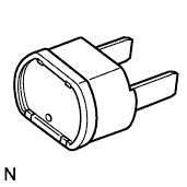 |  | CIRCUIT BREAKER | CB |
CLIPS
The removal and installation methods of typical clips used for vehicle body parts are shown in the table below.
| Shape (Example) | Removal/Installation |
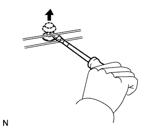
 | 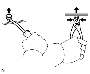 Remove clips with clip remover or pliers. |
 |  Remove fasteners with clip remover or screwdriver. |
 | 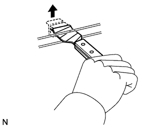 Remove clips with wide scraper to prevent panel damage. |
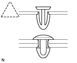
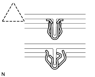
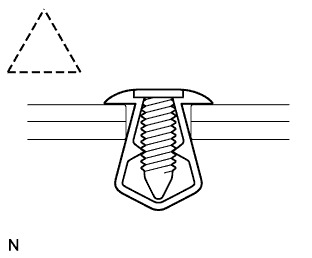
 | 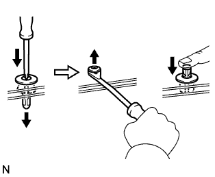 Remove clips by pushing center pin through and prying out shell. |
 | 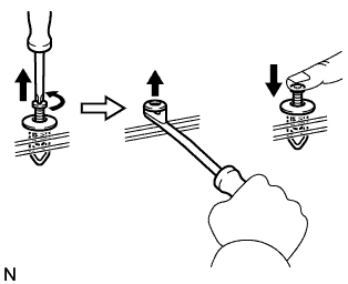 Remove clips by unscrewing center pin and prying out shell. |
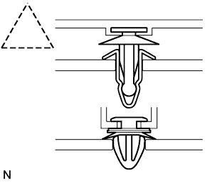
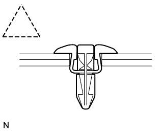
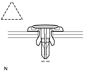 |  Remove clips by prying out pin and then prying out shell. |
CLAWS
The removal and installation methods of typical claws used for vehicle body parts are shown in the table below.
| Shape (Example) | Illustration | Procedures |
 |  |
|
 |  |
|
 |  |
|
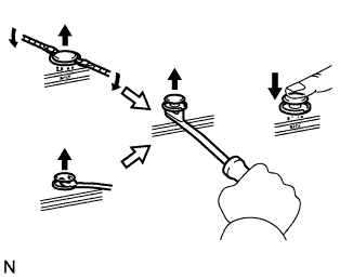
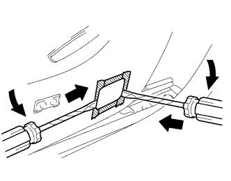
REMOVAL AND INSTALLATION OF VACUUM HOSES
 |
To disconnect a vacuum hose, pull and twist from the end of the hose. Do not pull from the middle of the hose as this may damage the hose.
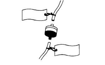 |
When disconnecting vacuum hoses, use tags to identify where they should be reconnected.
After completing any hose related repairs, double check that the vacuum hoses are properly connected. The label under the hood shows the proper layout.
When using a vacuum gauge, never force the hose onto a connector that is too large. If a hose has been stretched, air may leak. Use a step-down adapter if necessary.
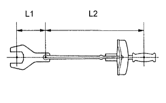 |
TORQUE WHEN USING TORQUE WRENCH WITH EXTENSION TOOL
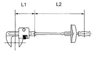 |
Use the formula below to calculate special torque values for situations where SST or an extension tool is combined with the torque wrench.
| T' | Reading of torque wrench {N*m (kgf*cm, ft.*lbf)} |
| T | Torque {N*m (kgf*cm, ft.*lbf)} |
| L1 | Length of SST or extension tool {cm (in.)} |
| L2 | Length of torque wrench {cm (in.)} |
| 2.PRECAUTIONS FOR HIGH-VOLTAGE CIRCUIT INSPECTION AND SERVICE |
Article 59 of the Occupational Safety and Health Law and Article 36 of the Occupational Safety and Health Regulations require technicians who inspect and service high-voltage circuits to undergo special training.
All high-voltage wire harness connectors are colored orange. The HV battery and other high-voltage components have "High Voltage" caution labels. Do not carelessly touch these wires and components.
 |
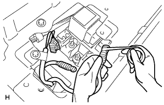
Before inspecting or servicing the high-voltage system, be sure to follow safety measures, such as wearing insulated gloves and removing the service plug to prevent electrocution. Carry the removed service plug in your pocket to prevent other technicians from reinstalling it while your are servicing the vehicle.
After removing the service plug, wait 5 minutes before touching any of the high-voltage connectors and terminals.
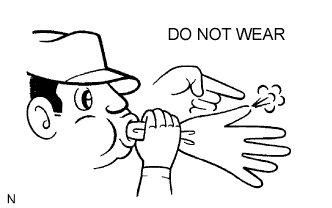 |
Before wearing insulated gloves, make sure that they are not cracked, ruptured, torn, or damaged in any way. Do not wear wet insulated gloves.
When servicing the vehicle, do not carry metal objects like mechanical pencils or scales that can be dropped accidentally and cause a short circuit.
Before touching a bare high-voltage terminal, wear insulated gloves and use a tester to make sure that the terminal voltage is 0 V.
 |
After disconnecting or exposing a high-voltage connector or terminal, insulate it immediately using gum tape.
The screw of a high-voltage terminal should be tightened firmly to the specified torque. Both insufficient and excessive torque can cause failure.
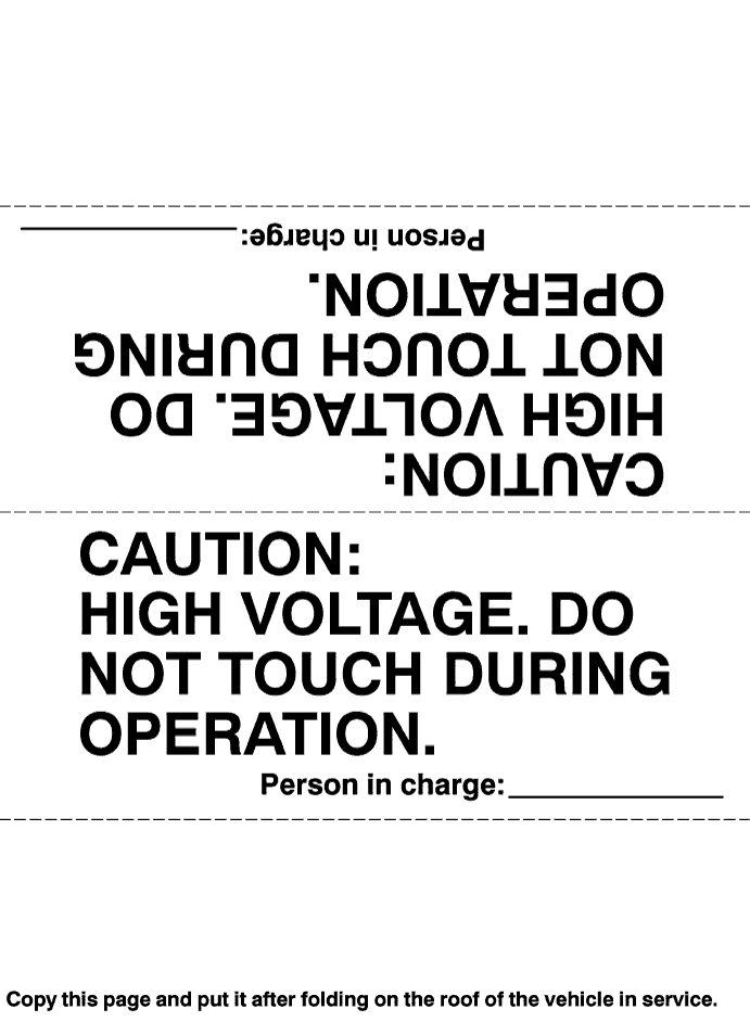
Use the "CAUTION: HIGH VOLTAGE. DO NOT TOUCH DURING OPERATION" sign to notify other engineers that a high-voltage system is being inspected and/or repaired.
After servicing the high-voltage system and before reinstalling the service plug, check again that you have not left a part or tool inside, that the high-voltage terminal screws are firmly tightened, and that the connectors are correctly connected.
Do not place the battery upside down while removing and installing it.
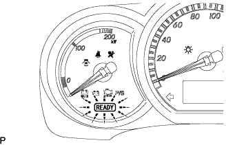
| 3.ACTIONS TO BE TAKEN WHEN THE WARNING LIGHT IS LIT |
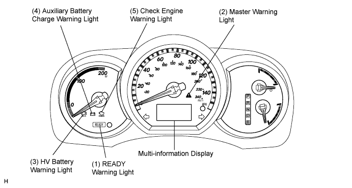
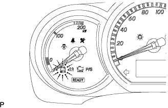
If one of the warning lights (2) to (5) becomes lit, connect an intelligent tester to the DLC3 connector to check the DTCs (Diagnostic Trouble Codes). Then, refer to the applicable troubleshooting steps in this manual to inspect and repair the affected area. The foregoing actions are also required if the READY light does not illuminate when the vehicle is first started.
| Warning Light | Vehicle Condition |
| (1) READY (TO DRIVE) | Illuminates when the ignition switch is turned to the START position, this indicates that the vehicle is ready to be driven. |
| (2) Master Warning Light | Blinks, illuminates, or sounds a buzzer that is synchronized with the warning light of the multi-display.
|
| (3) HV Battery Warning Light |
|
| (4) Auxiliary Battery Charge Warning Light | Illuminates when there is a malfunction in the charging system. (Be sure to check the DTC (Diagnostic Trouble Code) if this light illuminates together with MASTER WARNING.) |
| (5) Check Engine Warning Light | Illuminates when there is a malfunction in the engine control system. (Illuminates with the ignition switch ON and the READY light OFF.) |
| 4.ACTIONS TO BE TAKEN WHEN BATTERIES ARE DEPLETED |
Perform this procedure when the auxiliary battery is fully depleted.
Move the shift lever to the P position and engage the parking brake.
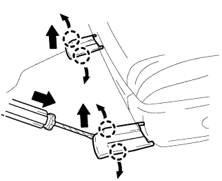
Remove the key from the ignition switch
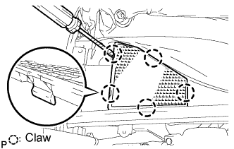 |
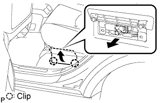
Using a screwdriver, disengage the 5 claws to remove the cowl top silencer pad RH.
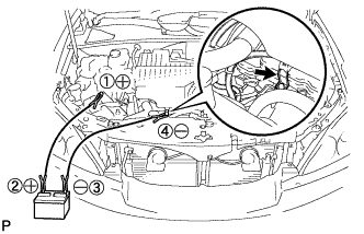 |
Using a booster cable, connect the 12 V battery of the rescue vehicle and the auxiliary battery of the stalled vehicle, as shown in the illustration.
| Connecting Sequence | Connecting Location |
| 1 | Positive battery terminal of stalled vehicle |
| 2 | Positive battery terminal of rescue vehicle |
| 3 | Negative battery terminal of rescue vehicle |
| 4 | Nut on the front suspension support RH of stalled vehicle |
Start the engine of the rescue vehicle and run the engine at a speed slightly higher than usual.
 |
Put the vehicle into the READY-on state to start the hybrid system.
When the hybrid vehicle battery is depleted:
Using a THS charger, recharge the hybrid vehicle battery.
| 5.INSPECTION MODE |
Change to the inspection mode.
| 6.SPECIAL NOTES FOR VEHICLE INSPECTION |
Vehicle conditions
Before activating inspection mode, turn the air conditioning off, start the engine with the shift lever in the P position, and check the engine stops within several seconds after starting (engine warm up check).
Activate inspection mode and inspect the vehicle.
| Test item | Inspection mode | Shift position |
| 1. Vehicle straight travelling test (side slip inspection) | 4WD inspection mode or normal | D |
| 2. Braking force test | 4WD inspection mode or normal | N |
| 3. Speedometer test | 2WD inspection mode | D |
| 4. Exhaust gas test (idling) | 4WD inspection mode | P |
| 5. Headlight test | 4WD inspection mode or normal | P |
Reset inspection mode immediately after completion of inspection.
Special notes for speedometer test
Depress the accelerator pedal slowly and gradually accelerate the vehicle. Make a measurement.
After the measurement, use the brake to gradually decelerate the vehicle.
Special notes for using the chassis dynamometer
Always set an appropriate load before starting the test.
Activating inspection mode (Not using the intelligent tester)
Perform the following steps from (1) through (4) in 60 seconds.
Turn the ignition switch to the ON position.
Fully depress the accelerator pedal twice with the transmission in the P position.
Fully depress the accelerator pedal twice with the transmission in the N position.
Fully depress the accelerator pedal twice with the transmission in the P position.
Check that the HV system warning light flashes on the multi-information display.
Start the engine by turning the ignition switch while depressing the brake pedal.
Activating inspection mode (Using the intelligent tester)
Connect the intelligent tester to the DLC3.
Turn the ignition switch to the ON position.
Turn the intelligent tester on.
Select the following menu items: DIAGNOSIS / OBD / MOBD / HV ECU / ACTIVE TEST / INSPECTION MOD1 / ON.
Check that the HV system warning light flashes on the multi-information display and the master warning light is illuminated in the combination meter.
Start the engine by turning the ignition switch while depressing the brake pedal.
Deactivating inspection mode
Turn the ignition switch off. The HV main system turns off simultaneously.
| 7.ACTIONS TO BE TAKEN FOR VEHICLE DAMAGED BY IMPACT |
Items to be prepared or operation at the accident site
Actions to be taken at the accident site
Check the vicinity of the hybrid vehicle battery for any leakage of the electrolyte.
If damage to any of the high-voltage components and cable is suspected, cut the high-voltage circuit using the procedure on the following pages.
 |
Turn the ignition switch off.
Wear insulated gloves, and then remove the service plug.
Moving the damaged vehicle
If any of the following conditions are met, tow the vehicle away using a tow truck.
 |
Park the vehicle in a safe place.
Shift the shift lever to the "P" position, and engage the parking brake.
Turn the ignition switch off, and disconnect the power cable from the negative (-) terminal of the auxiliary battery.
Remove the service plug while wearing insulated gloves.
Actions required after moving the damaged vehicle
Procedure
If you see any liquid on the road surface, it could be highly alkaline electrolyte leakage.
Wear rubber gloves and goggles, neutralize the liquid with saturated boric acid solution, and then apply red litmus paper to the leak. Check that the paper does not turn blue. Wipe the neutralized liquid with a shop rag or piece of cloth.
Items to be prepared (when repairing damaged vehicles)
Precautions to be observed when servicing the damaged vehicle
Wear insulated or rubber gloves, goggles, and safety shoes.
Check the HV battery and immediate area for any electrolyte leakage.
Do not touch any leaked liquid because it could be highly alkaline electrolyte. Wear rubber gloves and goggles, neutralize the liquid with saturated boric acid solution, and then apply red litmus paper to the leak. Check that the paper does not turn blue. Wipe the neutralized liquid with a shop rag or piece of cloth.
Do not touch a bare cable that could be a high voltage cable. If the cable must be touched or if accidental contact is unavailable, follow the following instructions: 1) wear insulated or rubber gloves and goggles, 2) measure the voltage between the cable and the body ground using an electrical tester, and 3) insulate the cable using vinyl tape.
If damage to any of the high-voltage components and cables is suspected, cut the high-voltage circuit using the procedure below.
Turn the ignition switch off.
Wear insulated gloves, and then remove the service plug.
Precautions to be taken when disposing of the vehicle
Disposing of HV battery
When scrapping the vehicle, remove the HV battery from the vehicle and return it to the location specified by the manufacturer. Any damaged HV battery should also be returned to the specified location.
Precautions to be observed when towing
Tow the damaged vehicle with its front and rear wheels lifted off the ground.
Towing with the 4 wheels on the ground
| 8.FOR VEHICLES EQUIPPED WITH SRS AIRBAG AND SEAT BELT PRETENSIONER |
GENERAL NOTICE
As malfunctions of the SRS are difficult to confirm, the Diagnostic Trouble Codes (DTCs) become the most important source of information when troubleshooting. When troubleshooting the SRS, always check the DTCs before disconnecting the battery.
Work must be started at least 90 seconds after the ignition switch is turned off and after the cable is disconnected from the negative (-) battery terminal.
The SRS is equipped with a back-up power source. If work is started within 90 seconds after turning the ignition switch off and disconnecting the cable from the negative (-) battery terminal, the SRS may deploy.
When the cable is disconnected from the negative (-) battery terminal, clock and audio system memory is erased. Before starting work, make a note of the settings of each memory system. When work is finished, reset the clock and audio system as before.
In minor collisions where the SRS does not deploy, the steering pad, front passenger airbag assembly, driver side knee airbag assembly, front seat side airbag assembly, curtain shield airbag assembly and front seat outer belt assembly should be inspected before further use of the vehicle.
(Click here for steering pad)
(Click here for front passenger airbag assembly)
(Click here for front seat side airbag assembly)
(Click here for driver side knee airbag assembly)
(Click here for curtain shield airbag assembly)
(Click here for front seat outer belt assembly)
Never use SRS parts from another vehicle. When replacing parts, use new parts.
Before repairs, remove the airbag sensor assemblies if impacts are likely to be applied to the sensor during repairs.
Never disassemble and attempt to repair all airbag sensor assemblies and all airbag assemblies.
Replace the airbag sensor assemblies and the airbag assemblies if: 1) damage has occurred from being dropped, or 2) cracks, dents or other defects in the case, bracket or connector are present.
Do not directly expose the airbag sensor assembly or airbag assembly to hot air or flames.
Use a voltmeter / ohmmeter with high impedance (minimum=10 kΩ) for troubleshooting electrical circuits.
Information labels are attached to the SRS components. Follow the instructions on the labels.
After work on the SRS is completed, check the SRS warning light.
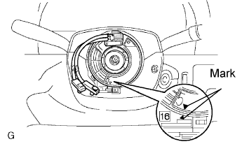 |
SPIRAL CABLE
The steering wheel must be fitted correctly to the steering column with the spiral cable at the neutral position, as cable disconnection and other problems may occur. Refer to the information about correct installation of the steering wheel (Click here).
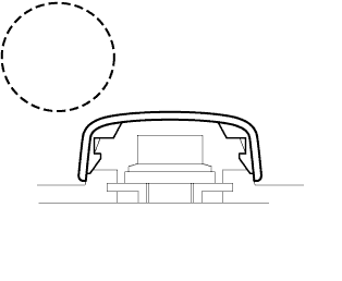
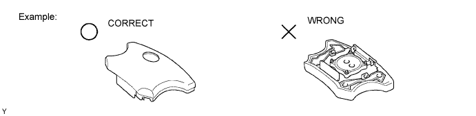
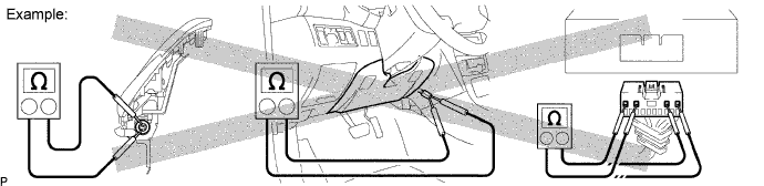
STEERING PAD
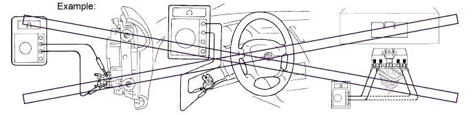
Always place a removed or new steering pad surface upward as shown in the illustration. Placing the horn button with the pad surface facing down could cause a serious accident if the airbag inflates. Also, do not place anything on top of the horn button.
Never measure the resistance of the airbag squib. This may cause the airbag to inflate, which could cause serious injury.
Grease or detergents of any kind should not be applied to the horn button.
Store the horn button assembly in an area where the ambient temperature is below 93°C (200°F), the humidity is not high and there is no electrical noise.
When using electric welding anywhere on the vehicle, disconnect the airbag ECU connectors (4 pins). These connectors contain shorting springs. This feature reduces the possibility of the airbag deploying due to current entering the squib wiring.
When disposing of the vehicle or the horn button assembly by itself, the airbag should be deployed using SST before disposal (Click here). Activate the airbag in a safe place away from electrical noise.
FRONT PASSENGER AIRBAG ASSEMBLY
Always place a removed or new front passenger airbag assembly with the pad surface facing upward as shown in the illustration. Placing the airbag assembly with the airbag inflation direction facing down could cause a serious accident if the airbag inflates.
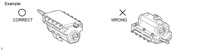
Never measure the resistance of the airbag squib. This may cause the airbag to inflate, which could cause serious injury.
Grease or detergents of any kind should not be applied to the front passenger airbag assembly.
Store the airbag assembly in an area where the ambient temperature is below 93°C (200°F), the humidity is not high and there is no electrical noise.
When using electric welding anywhere on the vehicle, disconnect the airbag ECU connectors (4 pins). These connectors contain shorting springs. This feature reduces the possibility of the airbag deploying due to current entering the squib wiring.
When disposing of the vehicle or the airbag assembly unit by itself, the airbag should be deployed using SST before disposal (Click here). Activate in a safe place, away from electrical noise.
DRIVER SIDE KNEE AIRBAG ASSEMBLY AND FRONT PASSENGER SIDE KNEE AIRBAG ASSEMBLY
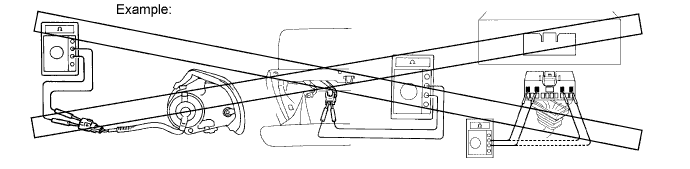
Always place a removed or new knee airbag assembly with the airbag inflation direction facing upward. Placing the airbag assembly with the airbag inflation direction facing downward could cause a serious accident if the airbag inflates.
Never measure the resistance of the airbag squib. This may cause the airbag to inflate, which could cause serious injury.
Grease or detergents of any kind should not be applied to the knee airbag assembly.
Store the knee airbag assembly where the ambient temperature is below 93°C (200°F), the humidity is not high and there is no electrical noise.
When using electric welding anywhere on the vehicle, disconnect the airbag ECU connectors (2 pins). These connectors contain shorting springs. This feature reduces the possibility of the airbag deploying due to current entering the squib wiring.
When disposing of a vehicle or knee airbag assembly unit by itself, the airbag should be inflated using SST before disposal (Click here). Activate in a safe place, away from electrical noise.
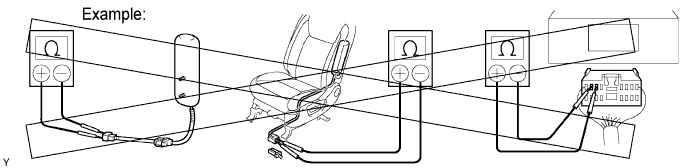
FRONT SEAT SIDE AIRBAG ASSEMBLY
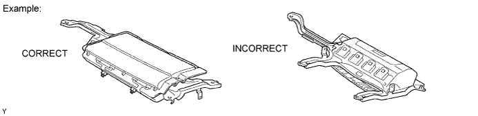
Always place a removed or new front seat side airbag assembly with the airbag inflation direction facing up.
Never measure the resistance of the airbag squib. This may cause the airbag to inflate, which could cause serious injury.
Grease or detergents of any kind should not be applied to the front seat side airbag assembly.
Store the airbag assembly in an area where the ambient temperature is below 93°C (200°F), the humidity is not high and there is no electrical noise.
When using electric welding anywhere on the vehicle, disconnect the airbag ECU connectors (2 pins). These connectors contain shorting springs. This feature reduces the possibility of the airbag deploying due to current entering the squib wiring.
When disposing of a vehicle or the airbag assembly unit by itself, the airbag should be deployed using SST before disposal (Click here). Activate in a safe place away from electrical noise.
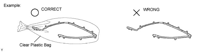
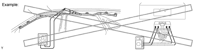
CURTAIN SHIELD AIRBAG ASSEMBLY
Always place a removed or new curtain shield airbag assembly in a clear plastic bag, and keep it in a safe place.
Never measure the resistance of the airbag squib. This may cause the airbag to inflate, which could cause serious injury.
Grease or detergents of any kind should not be applied to the curtain shield airbag assembly.
Store the airbag assembly in an area where the ambient temperature is below 93°C (200°F), the humidity is not high and there is no electrical noise.
When using electric welding anywhere on the vehicle, disconnect the airbag ECU connectors (4 pins). These connectors contain shorting springs. This feature reduces the possibility of the airbag deploying due to current entering the squib wiring.
When disposing of a vehicle or the airbag assembly unit by itself, the airbag should be deployed using SST before disposal (Click here). Activate in a safe place away from electrical noise.
FRONT SEAT OUTER BELT ASSEMBLY AND REAR SEAT OUTER BELT ASSEMBLY (SEAT BELT PRETENSIONER)
Never measure the resistance of the seat outer belt. This may cause the pretensioner of the seat belt to activate, which could cause serious injury.
Never disassemble the seat outer belt.
Never install the seat outer belt on another vehicle.
Store the seat outer belt in an area where the ambient temperature is below 80°C (176°F), the humidity is not high and there is no electrical noise.
When using electric welding anywhere on the vehicle, disconnect the airbag ECU connectors (2 pins). These connectors contain shorting springs. This feature reduces the possibility of the airbag deploying due to current entering the squib wiring.
When disposing of a vehicle or the seat outer belt unit by itself, the seat outer belt should be activated before disposal (Click here). Activate in a safe place away from electrical noise.
As the seat outer belt is hot after being activated, allow some time for it to cool down sufficiently before disposal. Never apply water to cool down the seat outer belt.
Grease, detergents, oil or water should not be applied to the front seat outer belt.
AIRBAG SENSOR ASSEMBLY
Never reuse an airbag sensor assembly that has been involved in a collision where the SRS has deployed.
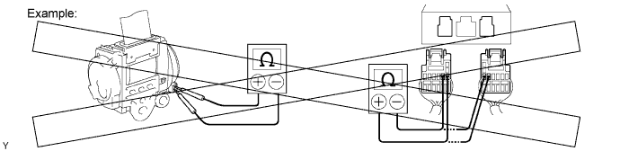
The connectors to the airbag sensor assembly should be connected or disconnected with the sensor placed on the floor. If the connectors are connected or disconnected while the airbag sensor assembly is not placed on the floor, the SRS may activate.
Work must be started at least 90 seconds after the ignition switch is turned off and the cable is disconnected from the negative (-) battery terminal, even if only loosening the set bolts of the airbag sensor assembly.
WIRE HARNESS AND CONNECTOR
The SRS wire harness is integrated with the instrument panel wire harness assembly. All the connectors in the system are a standard yellow color. If the SRS wire harness becomes disconnected or the connector becomes broken, repair or replace it.
| 9.ELECTRONIC CONTROL |
 |
REMOVAL AND INSTALLATION OF BATTERY TERMINAL
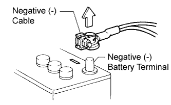
Before performing electronic work, disconnect the cable from the negative (-) battery terminal to prevent component and wire damage caused by accidental short circuits.
When disconnecting the cable, turn the ignition switch and headlight dimmer switch off and loosen the cable nut completely. Perform these operations without twisting or prying the cable. Then disconnect the cable.
Clock settings, radio settings, audio system memory, DTCs and other data are erased when the cable is disconnected from the negative (-) battery terminal. Write down any necessary data before disconnecting the cable.
 |
HANDLING OF ELECTRONIC PARTS
Do not open the cover or case of the ECU unless absolutely necessary. If the IC terminals are touched, the IC may be rendered inoperative by static electricity.
Do not pull the wires when disconnecting electronic connectors. Pull the connector itself.
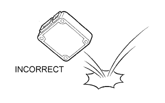
Do not drop electronic components, such as sensors or relays. If they are dropped on a hard surface, they should be replaced.
When cleaning the engine with steam, protect the electronic components, air filter and emission-related components from water.
Never use an impact wrench to remove or install temperature switches or temperature sensors.
When measuring the resistance between terminals of a wire connector, insert the tester probe carefully to prevent terminals from bending.
| 10.REMOVAL AND INSTALLATION OF FUEL CONTROL PARTS |
PLACE FOR REMOVING AND INSTALLING FUEL SYSTEM PARTS
Work in a location with good air ventilation that does not have welders, grinders, drills, electric motors, stoves, or any other ignition sources.
Never work in a pit or near a pit as vaporized fuel will collect in those places.
REMOVING AND INSTALLING FUEL SYSTEM PARTS
Prepare a fire extinguisher before starting the operation.
To prevent static electricity, install a ground wire to the fuel changer, vehicle and fuel tank, do not spray the surrounding area with water. Be careful when performing work in this area, as the work surface will become slippery. Do not clean up gasoline spills with water, as this may cause the gasoline to spread, and possibly create a fire hazard.
Avoid using electric motors, working lights and other electric equipments that can cause sparks or high temperatures.
Avoid using iron hammers as they may create sparks.
Dispose of fuel-contaminated cloth separately using a fire resistant container.
| 11.REMOVAL AND INSTALLATION OF ENGINE INTAKE PARTS |
 |
If any metal particles enter inlet system parts, this may damage the engine.
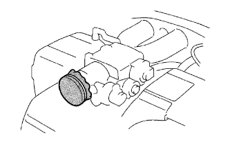
When removing and installing inlet system parts, cover the openings of the removed parts and engine openings. Use gummed tape or other suitable materials.
When installing inlet system parts, check that no metal particles have entered the engine or the installed parts.
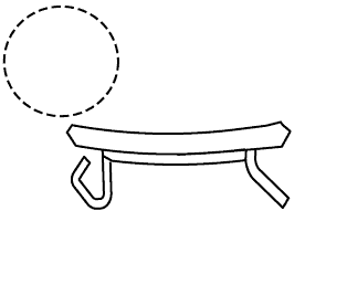
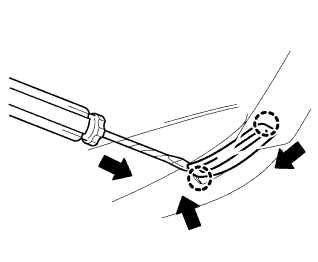
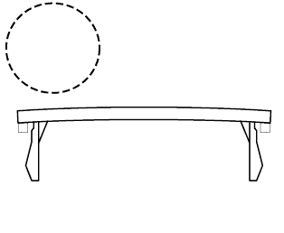
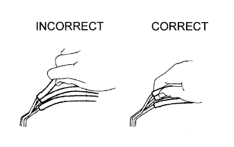
| 12.HANDLING OF HOSE CLAMPS |
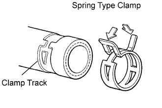 |
Before removing the hose, check the clamp position so that it can be reinstalled in the same position.
Replace any deformed or dented clamps with new ones.
When reusing a hose, attach the clamp on the clamp track portion of the hose.
For a spring type clamp, you may want to spread the tabs slightly after installation by pushing in the direction of the arrows as shown in the illustration.
| 13.FOR VEHICLES EQUIPPED WITH MOBILE COMMUNICATION SYSTEMS |
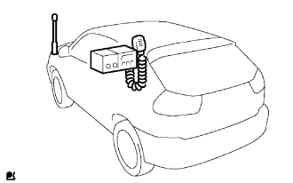 |
Install the antenna far away from the ECU and sensors of the vehicle electronic systems as possible.
Install an antenna feeder at least 20 cm (7.87 in.) away from the ECU and sensors of the vehicle electronic systems. For details about ECU and sensors locations, refer to the section on the applicable components.
Keep the antenna and feeder separate from other wirings as much as possible. This will prevent signals sent from the communication equipment from affecting vehicle equipment and vice-versa.
Check that the antenna and feeder are correctly adjusted.
Do not install any high-powered mobile communication system.
| 14.WHEN SERVICING FULL-TIME 4WD VEHICLES |
 |
The full-time 4WD LEXUS RX400H is equipped with the center differential system.
If incorrect preparations or test procedures are used, the test will not only be unsuccessful, but may be dangerous as well.
Therefore, before beginning any such servicing or test, be sure to check the following items:
Whether the tires are touching the ground or jacked up
Transaxle gear position
Maximum testing vehicle speed
Maximum testing time
Before Beginning Test
This vehicle does not have a Center Diff. Lock Mode or 4WD (Normal) Mode which allows only the front or rear wheel to be rotated.
The test method for this vehicle is different from that for vehicles equipped with the Center Diff. Lock Mode or 4WD (Normal) Mode, so make sure to use the correct test method.
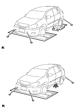
Braking Force Test (Vehicle Speed : Below 0.5 km/h or 0.3 mph)
When performimg low-speed type brake tester measurements, observe the following instructions:
Position the wheels to be tested (front or rear) on the tester.
Shift the transaxle shift lever to the "N" position.
Idle the engine, operate the brake booster and perform the test.
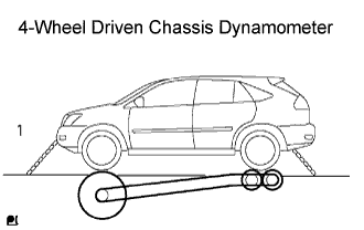 |
Speedometer Test or Other Tests
| No. | Chassis Dynamometer Type | Vehicle Speed and Test Time | Propeller shaft |
| 1 | 4-Wheel Driven Chassis Dynamometer | No restriction | Normal (Do not remove) |
On-Vehicle Wheel Balancing
When doing on-vehicle wheel balancing on a full-time 4WD vehicle, to prevent the wheels from each other (which could damage the center differential), always observe the following precautions:
 |
All 4 wheels should be jacked up, clearing the ground completely.
The parking brake lever should be fully released.
None of the brakes should be allowed to drag.
The wheels should be driven on the wheel balancer with the engine running.
Avoid sudden acceleration, deceleration and braking.
Carry out wheel balancing with the transaxle in the D position.
| 15.FOR VEHICLES EQUIPPED WITH VEHICLE STABILITY CONTROL (VSC) SYSTEM |
 |
NOTICES WHEN USING DRUM TESTER
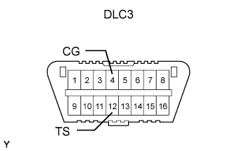
Before beginning testing, disable the VSC. To disable the VSC, turn the ignition switch off and connect SST to terminals TS and CG of the DLC3.
NOTICES OF RELATED OPERATIONS TO VSC
Do not carry out unnecessary installation and removal as it might affect the adjustment of VSC related parts.
Be sure to follow the instructions for work preparation and final confirmation of proper operation of the VSC system.
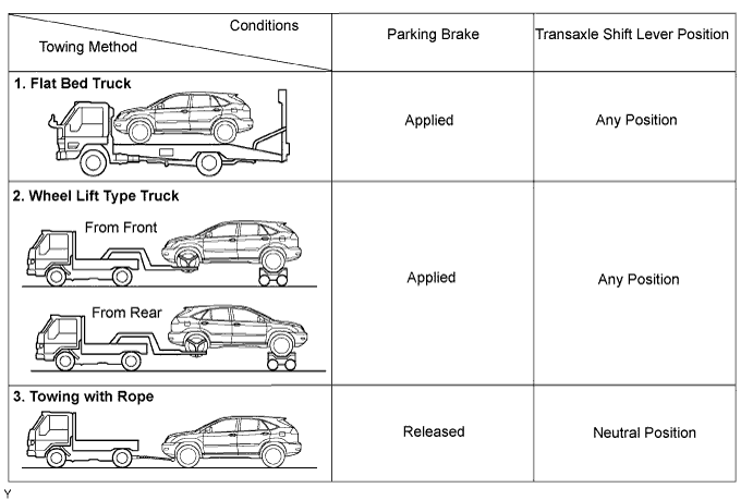
| 16.WHEN TOWING FULL-TIME 4WD VEHICLES |
Use one of the methods shown below to tow the vehicle.
If the vehicle has trouble with the chassis or drive train, use method 1 (flat bed truck).
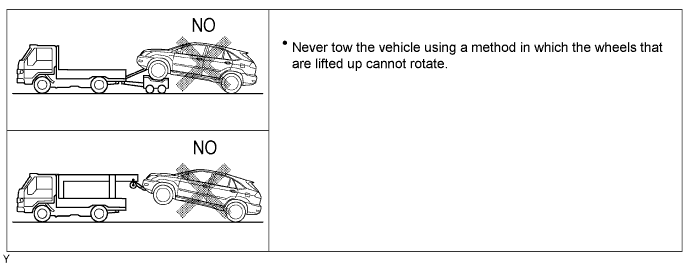
The towing methods shown below are dangerous and can damage the vehicle, so do not use them.
| 17.FOR VEHICLES EQUIPPED WITH CATALYTIC CONVERTER |
Use only unleaded gasoline.
Avoid idling the engine for more than 20 minutes.
Avoid performing unnecessary spark jump tests.
Perform a spark jump test only when absolutely necessary. Perform this test as rapidly as possible.
While testing, never race the engine.
Avoid a prolonged engine compression measurement. Engine compression measurements must be performed as rapidly as possible.
Do not run the engine when the fuel tank is nearly empty. This may cause the engine to misfire and create an extra load on the converter.
