DTC P0136 Oxygen Sensor Circuit Malfunction (Bank 1 Sensor 2) |
DTC P0137 Oxygen Sensor Circuit Low Voltage (Bank 1 Sensor 2) |
DTC P0138 Oxygen Sensor Circuit High Voltage (Bank 1 Sensor 2) |
DTC P0156 Oxygen Sensor Circuit Malfunction (Bank 2 Sensor 2) |
DTC P0157 Oxygen Sensor Circuit Low Voltage (Bank 2 Sensor 2) |
DTC P0158 Oxygen Sensor Circuit High Voltage (Bank 2 Sensor 2) |
| DTC No. | DTC Detection Condition | Trouble Area |
| P0136 P0156 |
|
|
| P0137 P0157 |
|
|
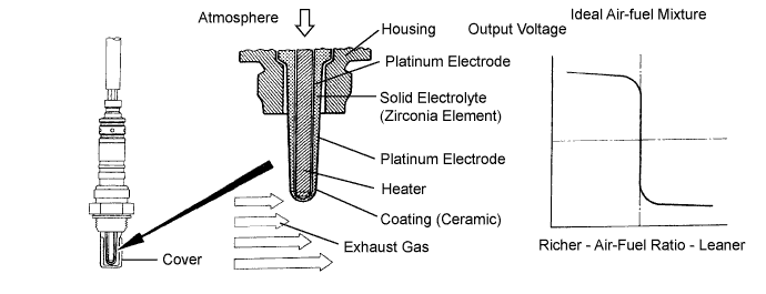
| P0138 P0158 | Out put voltage is more than 0.59 V for 20 seconds or more when air fuel ratio is 14.9 or more. (2 trip detection logic) |
|
| Tester Display (Sensor) | Injection Volume | Status | Voltage |
| AFS B1S1 or AFS B2S1 (A/F) | +25 % | Rich | Less than 3.0 |
| AFS B1S1 or AFS B2S1 (A/F) | -12.5 % | Lean | More than 3.35 |
| O2S B1S2 or O2S B2S2 (HO2) | +25 % | Rich | More than 0.55 |
| O2S B1S2 or O2S B2S2 (HO2) | -12.5 % | Lean | Less than 0.4 |
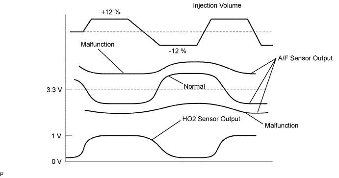
| Case | A/F Sensor (Sensor 1) Output Voltage | HO2 Sensor (Sensor 2) Output Voltage | Main Suspected Trouble Area | ||
| 1 | Injection Volume +25 % -12.5 % |  | Injection Volume +25 % -12.5 % | | - |
| Output Voltage More than 3.35 V Less than 3.0 V |  | Output Voltage More than 0.55 V Less than 0.4 V |  | ||
| 2 | Injection Volume +25 % -12.5 % | | Injection Volume +25 % -12.5 % | |
|
| Output Voltage Almost no reaction |  | Output Voltage More than 0.55 V Less than 0.4 V | | ||
| 3 | Injection Volume +25 % -12.5 % | | Injection Volume +25 % -12.5 % | |
|
| Output Voltage More than 3.35 V Less than 3.0 V | | Output Voltage Almost no reaction | | ||
| 4 | Injection volume +25 % -12.5 % | | Injection Volume +25 % -12.5 % | |
|
| Output Voltage Almost no reaction | | Output Voltage Almost no reaction | | ||
| 1.READ OUTPUT DTC |
Connect the intelligent tester to the DLC3.
Turn the ignition switch ON and turn the tester ON.
Enter the following menus: Powertrain / Engine / DTC.
Read DTCs.
| Display (DTC Output) | Proceed to |
| P0138 or P0158 | A |
| P0136 or P0156 | B |
|
| ||||
| A | |
| 2.READ VALUE USING INTELLIGENT TESTER (OUTPUT VOLTAGE OF HEATED OXYGEN SENSOR) |
Connect the intelligent tester to the DLC3.
Put the engine in inspection mode (Click here).
Start the engine.
Turn the tester ON.
Enter the following menus: Powertrain / Engine / Data List / O2S B1S2 or O2S B2S2.
Allow the engine to idle.
Read the Heated Oxygen (HO2) sensor output voltage while idling.
| HO2 Sensor Output Voltage | Proceed to |
| More than 1.2 V | A |
| Less than 1.0 V | B |
|
| ||||
| A | |
| 3.CHECK HARNESS AND CONNECTOR (CHECK FOR SHORT) |
 |
Turn the engine switch off and wait for 5 minutes.
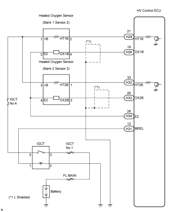
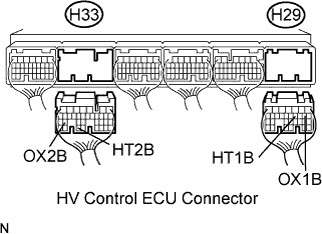
Disconnect the H29 and H33 HV Control ECU connector.
Measure the resistance between the terminals of the HV Control ECU.
| Tester Connection | Specified Condition |
| HT1B (H29-21) - OX1B (H29-19) | 10 kΩ or higher |
| HT2B (H33-33) - OX2B (H33-26) | 10 kΩ or higher |
Reconnect the ECM connector.
|
| ||||
| OK | ||
| ||
| 4.INSPECT HEATED OXYGEN SENSOR (CHECK FOR SHORT) |
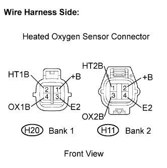 |
Disconnect the H11 or H20 HO2 sensor connector.
Measure the resistance of the HO2 sensor.
| Tester Connection | Specified Condition |
| +B (H20-2) - E (H20-4) | 10 kΩ or higher |
| +B (H20-2) -OX1B (H20-3) | 10 kΩ or higher |
| Tester Connection | Specified Condition |
| +B (H11-2) - E2 (H11-4) | 10 kΩ or higher |
| +B (H11-2) -OX2B (H11-3) | 10 kΩ or higher |
|
| ||||
| OK | |
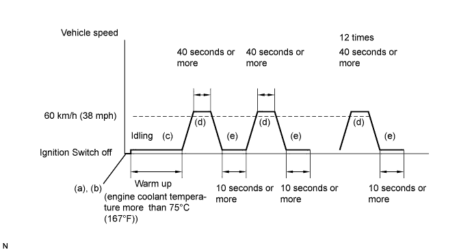
| 5.PERFORM CONFIRMATION DRIVING PATTERN |
| NEXT | |
| 6.CHECK WHETHER DTC OUTPUT RECURS (DTC P0138 or P0158) |
On the intelligent tester, enter the following menus: Powertrain / Engine / DTC.
Read DTCS.
| Display (DTC Output) | Proceed to |
| P0138 or P0158 | A |
| No output | B |
|
| ||||
| A | ||
| ||
| 7.READ VALUE USING INTELLIGENT TESTER (OUTPUT VOLTAGE OF HEATED OXYGEN SENSOR) |
Connect the intelligent tester to the DLC3.
Put the engine in inspection mode (Click here).
Start the engine.
Turn the tester ON.
Enter the following menus: Powertrain / Engine / Data List / O2S B1S2 or O2S B1S2.
After warming up the engine, run the engine at an engine speed of 2,500 rpm for 3 minutes.
Read the output voltage of the HO2 sensor when the engine rpm is suddenly increased.
|
| ||||
| OK | |
| 8.PERFORM CONFIRMATION DRIVING PATTERN |
| NEXT | |
| 9.CHECK WHETHER DTC OUTPUT RECURS (DTC P0136 or P0156) |
On the intelligent tester, enter the following menus: Powertrain / Engine / DTC.
Read DTCs.
| Display (DTC Output) | Proceed to |
| P0136 or P0156 | A |
| No output | B |
|
| ||||
| A | |
| 10.REPLACE HEATED OXYGEN SENSOR |
| NEXT | |
| 11.PERFORM CONFIRMATION DRIVING PATTERN |
| NEXT | |
| 12.CHECK WHETHER DTC OUTPUT RECURS (DTC P0136 or P0156) |
On the intelligent tester, enter the following menus: Powertrain / Engine/ DTC.
Read DTCs.
| Display (DTC Output) | Proceed to |
| P0136 or P0156 | A |
| No output | B |
|
| ||||
| A | |
| 13.PERFORM ACTIVE TEST USING INTELLIGENT TESTER (INJECTION VOLUME) |
Connect the intelligent tester to the DLC3.
Put the engine in inspection mode (Click here).
Start the engine.
Turn the tester ON.
Warm up the engine.
Enter the following menus: Powertrain / Engine / Active Test / Control the Injection Volume.
Change the fuel injection volume using the tester, monitoring the output voltage of Air-Fuel Ratio (A/F) and HO2 sensor displayed on the tester.
| Tester Display (Sensor) | Voltage Variation | Proceed to |
| AFS B1S1 (A/F) AFS B2S1 (A/F) | Alternates between more and less than 3.3 V | OK |
| AFS B1S1 (A/F) AFS B2S1 (A/F) | Remains at more than 3.3 V | NG |
| AFS B1S1 (A/F) AFS B2S1 (A/F)
| Remains at less than 3.3 V | NG |
|
| ||||
| OK | ||
| ||
| 14.CHECK EXHAUST GAS LEAKAGE |
|
| ||||
| OK | |
| 15.INSPECT HEATED OXYGEN SENSOR |
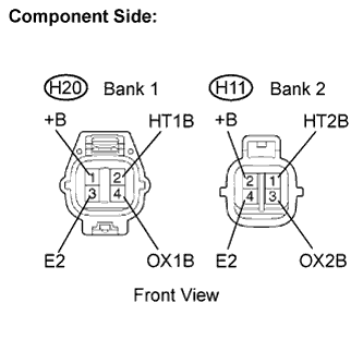 |
Disconnect the H11 or H20 HO2 sensor connector.
Measure the resistance of the HO2 sensor.
| Tester Connection | Specified Condition |
| +B (H20-2) - E (H20-4) | 10 kΩ or higher |
| +B (H20-2) - OX1B (H20-3) | 10 kΩ or higher |
| Tester Connection | Specified Condition |
| +B (H11-2) - E2 (H11-4) | 10 kΩ or higher |
| +B (H11-2) - OX2B (H11-3) | 10 kΩ or higher |
|
| ||||
| OK | |
| 16.INSPECT INTEGRATION RELAY (IGCT RELAY) |
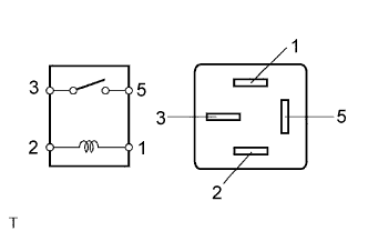 |
Remove the integration relay from the engine room R/B.
Measure the IGCT relay resistance.
| Terminal Connection | Specified Condition |
| 3 - 5 | 10 kΩ or higher |
| 3 - 5 | Below 1 Ω (When battery voltage applied to terminals 1 and 2) |
Reinstall the IGCT relay.
|
| ||||
| OK | |
| 17.CHECK HARNESS AND CONNECTOR (HEATED OXYGEN SENSOR - ECM) |
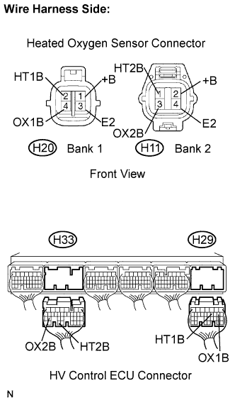 |
Disconnect the H11 or H20 HO2 sensor connector.
Turn the ignition switch ON.
Measure the voltage between the +B terminal of the HO2 sensor connector and body ground.
| Terminal Connection | Specified Condition |
| +B (H20-2) - Body ground | 9 to 14 V |
| +B (H11-2) - Body ground | 9 to 14 V |
Turn the engine switch off.
Disconnect the H29, H32 and H33 HV Control ECU connector.
Measure the resistance between terminals of the HO2 sensor and HV Control ECU.
| Terminal Connection | Specified Condition |
| HT1B (H20-1) - HT1B (H29-21) | Below 1 Ω |
| OX1B (H20-3) - OX1B (H29-19) | Below 1 Ω |
| E2 (H20-4) - E2 (H32-28) | Below 1 Ω |
| HT2B (H11-1) - HT2B (H33-33) | Below 1 Ω |
| OX2B (H11-3) - OX2B (H33-26) | Below 1 Ω |
| E2 (H11-4) - E2 (H32-28) | Below 1 Ω |
| Terminal Connection | Specified Condition |
| HT1B (H20-1) - HT1B (H29-21) - Body ground | 10 kΩ or higher |
| OX1B (H20-3) - OX1B (H29-19) - Body ground | 10 kΩ or higher |
| E2 (H20-4) - E2 (H32-28) - Body ground | 10 kΩ or higher |
| HT2B (H11-1) - HT2B (H33-33) - Body ground | 10 kΩ or higher |
| OX2B (H11-3) - OX2B (H33-26) - Body ground | 10 kΩ or higher |
| E2 (H11-4) - E2 (H32-28) - Body ground | 10 kΩ or higher |
Reconnect the HO2 sensor connector.
Reconnect the HV Control ECU connector.
|
| ||||
| OK | ||
| ||
