DTC P0340 Camshaft Position Sensor Circuit Malfunction |
DTC P0341 Camshaft Position Sensor "A" Circuit Range / Performance (Bank 1 or Single Sensor) |
DTC P0345 Camshaft Position Sensor "A" Circuit (Bank 2) |
DTC P0346 Camshaft Position Sensor "A" Circuit Range / Performance (Bank 2) |
| DTC No. | DTC Detection Condition | Trouble Area |
| P0340 P0345 |
|
|
| P0341 | While crankshaft rotates twice, VVT sensor signal is input to ECM 12 times or more. (1 trip detection logic) |
|
| P0346 | While crankshaft rotates twice, VVT sensor signal is input to ECM 5 times or more. (1 trip detection logic) |
|
| Item | Content |
| Terminals | NE+ - NE- VV1+ - NE- VV2+ - NE- |
| Equipment Settings | 5 V/Division, 20 ms/Division |
| Conditions | Cranking or idling |
| 1.CHECK ECU TERMINAL VOLTAGE (VV1+, VV2+, NE+ AND NE- TERMINALS) |
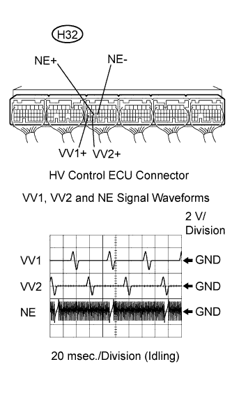 |
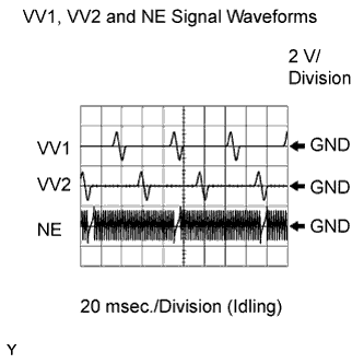
Inspect the HV Control ECU using an oscilloscope.
While the engine is idling, check the waveform between the terminals of the HV Control ECU connector.
| Tester Connection | Specified Condition |
| VV1+ (H32-27) - NE- (H32-24) | Correct waveform shown |
| VV2+ (H32-26) - NE- (H32-24) | Correct waveform shown |
| NE+ (H32-25) - NE- (H32-24) | Correct waveform shown |
|
| ||||
| OK | |
| 2.CHECK VVT SENSOR (SENSOR RESISTANCE) |
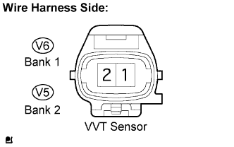 |
Disconnect the V4 or V5 VVT sensor connector.
Measure the resistance between the terminals of the sensor.
| Tester Connection | Specified Condition |
| 1 - 2 | 835 to 1,400 Ω at cold |
| 1 - 2 | 1,060 to 1,645 Ω at hot |
Reconnect the VVT sensor connector.
|
| ||||
| OK | |
| 3.CHECK HARNESS AND CONNECTOR (VVT SENSOR - HV CONTROL ECU) |
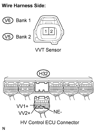 |
Disconnect the V4 or V5 VVT sensor connector.
Disconnect the H32 HV Control ECU connector.
Measure the resistance between the terminals of the VVT sensor and HV Control ECU.
| Tester Connection | Specified Condition |
| VVT sensor (V5-1) - VV1+ (H32-27) | Below 1 Ω |
| VVT sensor (V5-2) - NE- (H32-24) | Below 1 Ω |
| VVT sensor (V4-1) - VV2+ (H32-26) | Below 1 Ω |
| VVT sensor (V4-2) - NE- (H32-24) | Below 1 Ω |
| Tester Connection | Specified Condition |
| VVT sensor (V5-1) or VV1+ (H32-27) - Body ground | 10 kΩ or higher |
| VVT sensor (V5-2) or NE- (H32-24) - Body ground | 10 kΩ or higher |
| VVT sensor (V4-1) or VV2+ (H32-26) - Body ground | 10 kΩ or higher |
| VVT sensor (V4-2) or NE- (H32-24) - Body ground | 10 kΩ or higher |
Reconnect the VVT sensor connector.
Reconnect the HV Control ECU connector.
|
| ||||
| OK | |
| 4.CHECK SENSOR INSTALLATION (VVT SENSOR) |
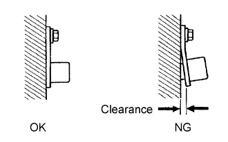 |
Check the CKP sensor installation.
|
| ||||
| OK | |
| 5.CHECK CAMSHAFT TIMING GEAR ASSEMBLY (TEETH OF PLATE) |
Check the teeth of the signal plate.
|
| ||||
| OK | ||
| ||
