DTC P0420 Catalyst System Efficiency Below Threshold (Bank 1) |
DTC P0430 Catalyst System Efficiency Below Threshold (Bank 2) |
| DTC No. | DTC Detection Condition | Trouble Area |
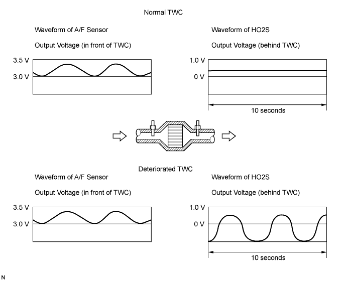
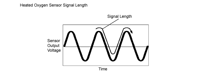
| P0420 | After engine and TWC warmed up, and while vehicle driven within set vehicle and engine speeds, waveform of Heated Oxygen (HO2) sensor (bank 1 sensor 2) alternates frequently between rich and lean (2 trip detection logic) |
|
| P0430 | After engine and catalyst are warmed up, and while vehicle is driven within set vehicle and engine speed ranges: Waveform of heated oxygen sensor (bank 2 sensor 2) alternates frequently between rich and lean (2 trip detection logic) |
|
| Case | A/F Sensor (Sensor 1) Output Voltage | HO2 Sensor (Sensor 2) Output Voltage | Main Suspected Trouble Area | ||
| 1 | Injection Volume +25 % -12.5 % |  | Injection Volume +25 % -12.5 % | | - |
| Output Voltage More than 3.35 V Less than 3.0 V |  | Output Voltage More than 0.55 V Less than 0.4 V |  | ||
| 2 | Injection Volume +25 % -12.5 % | | Injection Volume +25 % -12.5 % | |
|
| Output Voltage Almost no reaction |  | Output Voltage More than 0.55 V Less than 0.4 V | | ||
| 3 | Injection Volume +25 % -12.5 % | | Injection Volume +25 % -12.5 % | |
|
| Output Voltage More than 3.35 V Less than 3.0 V | | Output Voltage Almost no reaction | | ||
| 4 | Injection volume +25 % -12.5 % | | Injection Volume +25 % -12.5 % | |
|
| Output Voltage Almost no reaction | | Output Voltage Almost no reaction | | ||
| 1.CHECK ANY OTHER DTCS OUTPUT (IN ADDITION TO DTC P0420 AND/OR P0430) |
Connect the intelligent tester to the DLC3.
Turn the ignition switch ON and turn the tester ON.
Enter the following menus: Powertrain / Engine / DTC.
Read DTCs.
| Display (DTC output) | Proceed to |
| P0420 and/or P0430 | A |
| P0420 and/or P0430 and other DTCs | B |
|
| ||||
| A | |
| 2.PERFORM ACTIVE TEST USING INTELLIGENT TESTER (A/F CONTROL) |
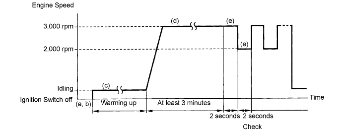
Connect the intelligent tester to the DLC3.
Put the engine in inspection mode (Click here).
Start the engine and turn the tester ON.
Warm up the engine at engine speed of 2,500 rpm for approximately 90 seconds.
On the tester, enter the following menus: Powertrain / Engine / Active Test / Control the Injection Volume for A/F Sensor.
Perform the A/F Control operation with the engine in an idling condition (press the Right or Left button to change the fuel injection volume.).
Monitor the output voltages of the A/F and HO2 sensors (AFS B1S1 and O2S B1S2 or AFS B2S1 and O2S B2S2) displayed on the tester.
| Tester Display (Sensor) | Injection Volume | Status | Voltage |
| AFS B1S1 or AFS B2S1 (A/F) | +25 % | Rich | Less than 3.0 |
| AFS B1S1 or AFS B2S1 (A/F) | -12.5 % | Lean | More than 3.35 |
| O2S B1S2 or O2S B2S2 (HO2) | +25 % | Rich | More than 0.55 |
| O2S B1S2 or O2S B2S2 (HO2) | -12.5 % | Lean | Less than 0.4 |
| Status AFS B1S1 or AFS B2S1 | Status O2S B1S2 or O2S B2S2 | A/F Condition and A/F and HO2 Sensor Conditions | Misfire | Main Suspected Trouble Areas | Proceed to |
| Lean/Rich | Lean/Rich | Normal | - |
| A |
| Lean | Lean/Rich | A/F sensor malfunction | - |
| B |
| Rich | Lean/Rich | A/F sensor malfunction | May occur |
| B |
| Lean/Rich | Lean | HO2 sensor malfunction | - |
| C |
| Lean/Rich | Rich | HO2 sensor malfunction | - |
| C |
| Lean | Lean | Actual air-fuel ratio lean | May occur |
| A |
| Rich | Rich | Actual air-fuel ratio lean | - |
| A |
|
| ||||
|
| ||||
| A | |
| 3.CHECK FOR EXHAUST GAS LEAKAGE |
|
| ||||
| OK | ||
| ||
