DTC P2195 Oxygen (A/F) Sensor Signal Stuck Lean (Bank 1 Sensor 1) |
DTC P2196 Oxygen (A/F) Sensor Signal Stuck Rich (Bank 1 Sensor 1) |
DTC P2197 Oxygen (A/F) Sensor Signal Stuck Lean (Bank 2 Sensor 1) |
DTC P2198 Oxygen (A/F) Sensor Signal Stuck Rich (Bank 2 Sensor 1) |
| DTC No. | DTC Detection Condition | Trouble Area |
| P2195 P2197 |
|
|
| P2196 P2198 |
|
|
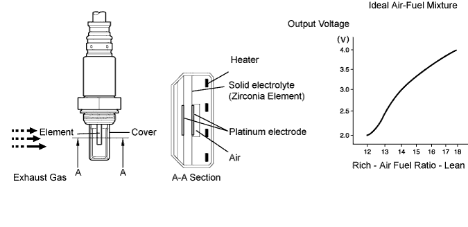
| Tester Display (Sensor) | Injection Volume | Status | Voltage |
| AFS B1S1 or AFS B2S1 (A/F) | +25 % | Rich | Less than 3.0 |
| AFS B1S1 or AFS B2S1 (A/F) | -12.5 % | Lean | More than 3.35 |
| O2S B1S2 or O2S B2S2 (HO2) | +25 % | Rich | More than 0.55 |
| O2S B1S2 or O2S B2S2 (HO2) | -12.5 % | Lean | Less than 0.4 |
| Case | A/F Sensor (Sensor 1) Output Voltage | HO2 Sensor (Sensor 2) Output Voltage | Main Suspected Trouble Areas | ||
| 1 | Injection Volume +25 % -12.5 % |  | Injection Volume +25 % -12.5 % | | - |
| Output Voltage More than 3.35 V Less than 3.0 V |  | Output Voltage More than 0.55 V Less than 0.4 V |  | ||
| 2 | Injection Volume +25 % -12.5 % | | Injection Volume +25 % -12.5 % | |
|
| Output Voltage Almost no reaction |  | Output Voltage More than 0.55 V Less than 0.4 V | | ||
| 3 | Injection Volume +25 % -12.5 % | | Injection Volume +25 % -12.5 % | |
|
| Output Voltage More than 3.35 V Less than 3.0 V | | Output Voltage Almost no reaction | | ||
| 4 | Injection volume +25 % -12.5 % | | Injection Volume +25 % -12.5 % | |
|
| Output Voltage Almost no reaction | | Output Voltage Almost no reaction | | ||
| 1.CHECK ANY OTHER DTCS OUTPUT (IN ADDITION TO P2195, P2196, 2197 OR P2198) |
Connect the intelligent tester to the DLC3.
Turn the ignition switch ON.
Turn the tester ON.
Enter the following menus: Powertrain / Engine / DTC.
Read DTCs.
| Display (DTC Output) | Proceed to |
| P2195, P2196, P2197, or P2198 | A |
| P2195, P2196, P2197, or P2198 and other DTCs | B |
|
| ||||
| A | |
| 2.READ VALUE USING INTELLIGENT TESTER (OUTPUT VOLTAGE OF A/F SENSOR) |
Connect the intelligent tester to the DLC3.
Put the engine in inspection mode (Click here).
Start the engine.
Turn the tester ON.
Warm up the Air-Fuel Ratio (A/F) sensor at an engine speed of 2,500 rpm for 90 seconds.
On the tester, enter the following menus: Powertrain / Engine / Active Test / Custom List / AFS B1S1 or AFS B2S1 and Engine Speed / Record.
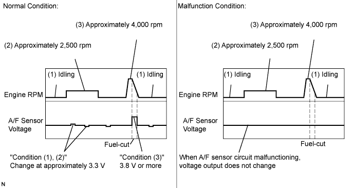
Check the A/F sensor voltage three times, when the engine is in each of the following conditions:
While idling (check for at least 30 seconds)
At an engine speed of approximately 2,500 rpm (without any sudden changes in engine speed)
Raise the engine speed to 4,000 rpm and then quickly release the accelerator pedal so that the throttle valve is fully closed.
| Condition | A/F Sensor Voltage Variation | Reference |
| (1) and (2) | Changes at approximately 3.3 V | Between 3.1 V and 3.5 V |
| (3) | Increases to 3.8 V or more | This occurs during engine deceleration (when fuel-cut performed) |
|
| ||||
| OK | |
| 3.INSPECT AIR FUEL RATIO SENSOR |
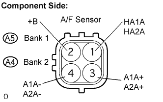 |
Disconnect the A4 or A5 A/F sensor connector.
Measure the resistance between the terminals of the A/F sensor connector.
| Tester Connection | Specified Condition |
| HA1A, HA2A (1) - +B (2) | 1.8 Ω to 3.4 Ω at 20°C (68°F) |
| HA1A, HA2A (1) - +B (2) | 10 kΩ or higher |
Reconnect the A/F sensor connector.
|
| ||||
| OK | |
| 4.INSPECT A/F RELAY |
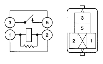 |
Remove the A/F relay from the engine room No. 2 relay block.
Measure the A/F relay resistance.
| Tester Connection | Specified Condition |
| 3 - 5 | 10 kΩ or higher |
| 3 - 5 | Below 1 Ω (when battery voltage applied to terminals 1 and 2) |
Reinstall the A/F HTR relay.
|
| ||||
| OK | |
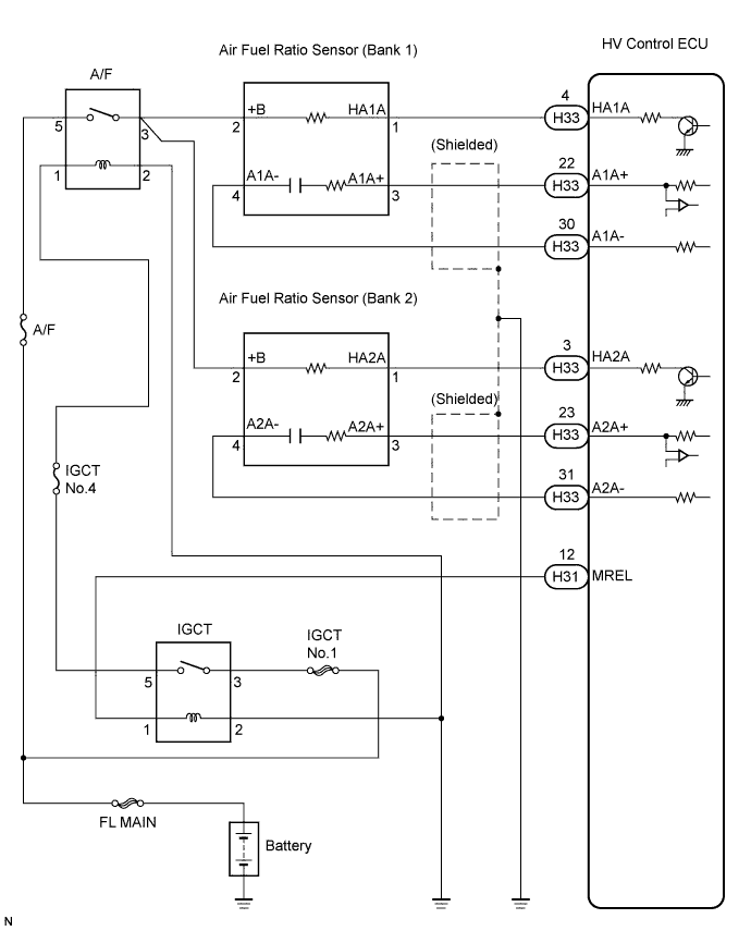
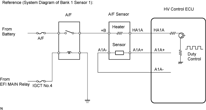
| 5.CHECK HARNESS AND CONNECTOR (A/F SENSOR - HV CONTROL ECU) |
 |
Disconnect the A4 and A5 A/F sensor connector.
Turn the ignition switch ON.
Measure the voltage between the +B terminal of the A/F sensor connector and body ground.
| Tester Connection | Specified Condition |
| +B (2) - Body ground | 9 to 14 V |
Turn the ignition switch off.
Disconnect the H33 HV Control ECU connector.
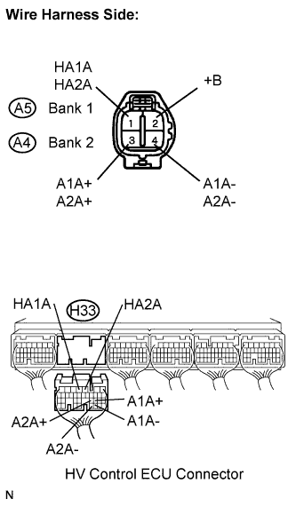
Measure the resistance between the terminals of the A/F sensor and HV Control ECU.
| Tester Connection | Specified Condition |
| HA1A ( A5-1) - HA1A (H33-4) | Below 1 Ω |
| A1A+ (A5-3) - A1A+ (H33-22) | Below 1 Ω |
| A1A- (A5-4) - A1A- (H33-30) | Below 1 Ω |
| HA2A (A4-1) - HA2A (H33-3) | Below 1 Ω |
| A2A+ (A4-3) - A2A+ (H33-23) | Below 1 Ω |
| A2A- (A4-4) - A2A- (H33-31) | Below 1 Ω |
| Tester Connection | Specified Condition |
| HA1A ( A5-1) or HA1A (H33-4) - Body ground | 10 kΩ or higher |
| A1A+ (A5-3) or A1A+ (H33-22) - Body ground | 10 kΩ or higher |
| A1A- (A5-4) or A1A- (H33-30) - Body ground | 10 kΩ or higher |
| HA2A (A4-1) or HA2A (H33-3) - Body ground | 10 kΩ or higher |
| A2A+ (A4-3) or A2A+ (H33-23) - Body ground | 10 kΩ or higher |
| A2A- (A4-4) or A2A- (H33-31) - Body ground | 10 kΩ or higher |
Reconnect the HV Control ECU connector.
Reconnect the A/F sensor connector.
|
| ||||
| OK | |
| 6.CHECK AIR INDUCTION SYSTEM |
Check the air induction system for vacuum leakage.
|
| ||||
| OK | |
| 7.CHECK FUEL PRESSURE |
Check the fuel pressure (Click here).
|
| ||||
| OK | |
| 8.INSPECT FUEL INJECTOR ASSEMBLY |
Check the injector injection (Click here).
|
| ||||
| OK | |
| 9.REPLACE AIR FUEL RATIO SENSOR |
| NEXT | |
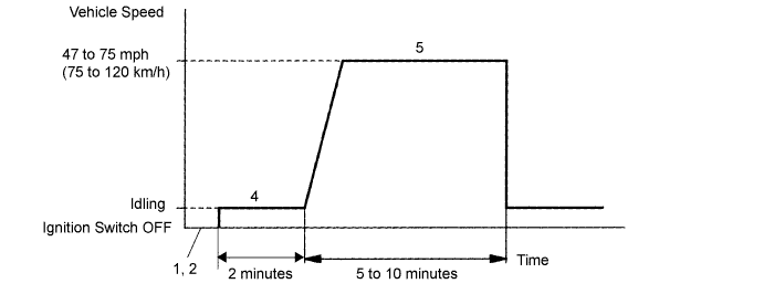
| 10.PERFORM CONFIRMATION DRIVING PATTERN |
| NEXT | |
| 11.CHECK WHETHER DTC OUTPUT RECURS (DTC P2195, P2196, P2197 OR P2198) |
Read DTCs using the intelligent tester.
Enter the following menus: Powertrain / Engine / DTC / Pending.
| Display (DTC Output) | Proceed to |
| No output | A |
| P2195, P2196, P2197 or P2198 | B |
|
| ||||
| A | |
| 12.CONFIRM WHETHER VEHICLE HAS RUN OUT OF FUEL IN PAST |
|
| ||||
| YES | ||
| ||
| 13.REPLACE AIR FUEL RATIO SENSOR |
| NEXT | |
| 14.PERFORM CONFIRMATION DRIVING PATTERN |
| NEXT | |
| 15.CHECK WHETHER DTC OUTPUT RECURS (DTC P2195, P2196, P2197 OR P2198) |
Connect the intelligent tester to the DLC3.
Turn the ignition switch ON and turn the tester ON.
Read DTCs using the intelligent tester.
Enter the following menus: Powertrain / Engine / DTC / Pending.
| Display (DTC Output) | Proceed to |
| No output | A |
| P2195, P2196, P2197 or P2198 (A/F sensor pending DTCs) | B |
|
| ||||
| A | ||
| ||
