MULTIPLEX COMMUNICATION SYSTEM > TERMINALS OF ECU |
| CHECK MULTIPLEX NETWORK GATEWAY ECU |
Disconnect the G1 ECU connector.
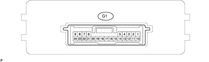
Measure the voltage and resistance of the wire harness side connector.
| Symbols (Terminal No.) | Wiring Color | Terminal Description | Condition | Specified Condition |
| BATT (G1-10) - GND (G1 24) | SB - W-B | +B (BATT) power supply | Always | 10 to 14 V |
| IG (G1-1) - Body ground | Y - Body ground | Ignition power supply | Ignition switch ON | 10 to 14 V |
| ACC (G1-2) - Body ground | L - Body ground | ACC power supply | Ignition switch ON | 10 to 14 V |
| SIL (G1-7) - Body ground | GR - Body ground | Bus ''+'' line | During transmission | Pulse generation |
| MPI1 (G1-4) - Body ground | GR - Body ground | MPX line | Always | 10 kΩ or higher |
| MPI2 (G1-13) - Body ground | O - Body ground | MPX line | Always | 10 kΩ or higher |
| MPD1 (G1-3) - Body ground | R - Body ground | MPX line | Always | 10 kΩ or higher |
| MPD2 (G1-12) - Body ground | R - Body ground | W-B - Body ground | Always | 10 kΩ or higher |
| GND (G1-24) - Body ground | W-B - Body ground | Ground | Always | Below 1 Ω |
| GTX- (G1-21) - Body ground | B - Body ground | AVC-LAN line | Always | 10 kΩ or higher |
| GTX+ (G1-6) - Body ground | R - Body ground | AVC-LAN line | Always | 10 kΩ or higher |
| CHECK INSTRUMENT PANEL JUNCTION BLOCK (MULTIPLEX NETWORK BODY ECU) |
Disconnect the 1E, 1D and 1F junction block connectors.
Disconnect the B7 ECU connector.
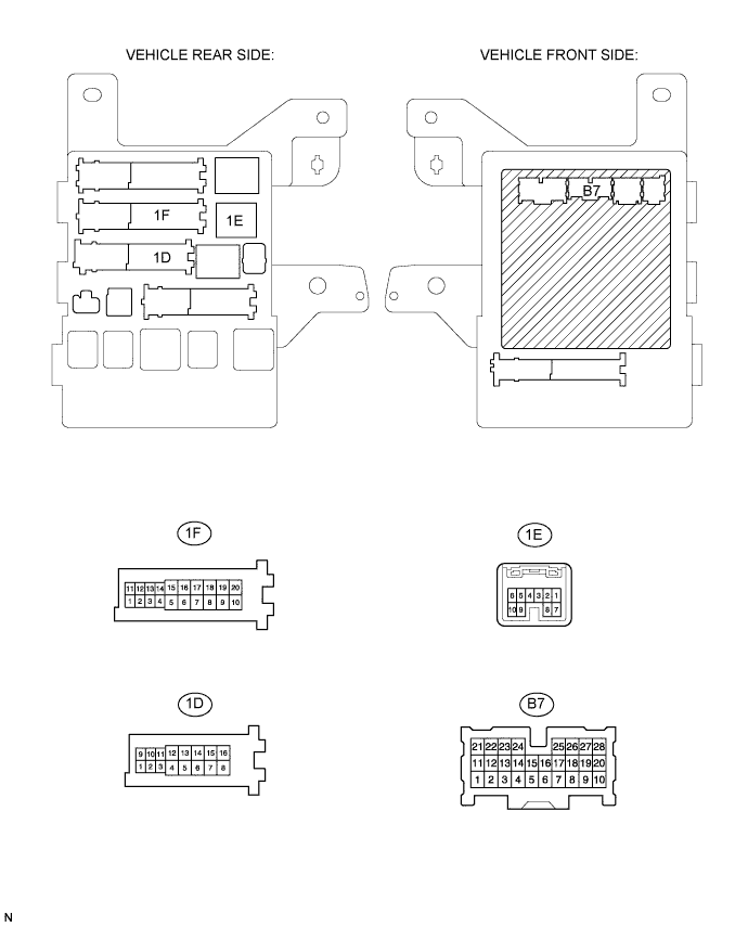
Measure the resistance and voltage of the wire harness side connectors.
| Symbols (Terminals No.) | Wiring Color | Terminal Description | Condition | Specified Condition |
| BECU (1D-10) - Body ground | SB - Body ground | +B (BECU) power supply | Always | 10 to 14 V |
| MPX1 (1E-7) - Body ground | BR - Body ground | MPX line | Always | 10 kΩ or higher |
| MPX2 (B7-21) - Body ground | O - Body ground | MPX line | Always | 10 kΩ or higher |
| GND1 (1F-10) - Body ground | W-B - Body ground | Ground | Always | Below 1 Ω |
| CHECK CENTER CLUSTER INTEGRATION PANEL (W/O LEXUS NAVIGATION SYSTEM) |
Disconnect the C4 panel connector.

Measure the voltage and resistance of the wire harness side connector.
| Symbols (Terminals No.) | Wiring Color | Terminal Description | Condition | Specified Condition |
| IG+ (C4-9) - Body ground | LG - Body ground | Ignition switch (on) signal | Ignition switch ON | 10 to 14 V |
| MPX+ (C4-5) - Body ground | L - Body ground | MPX line | Always | 10 kΩ or higher |
| MPX- (C4-12) - Body ground | R - Body ground | MPX line | Always | 10 kΩ or higher |
| GND (C4-7) - Body ground | W-B - Body ground | Ground | Always | Below 1 Ω |
| CHECK AUTO WIPER ECU |
Disconnect the A31 and A30 ECU connectors.
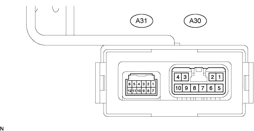
Measure the voltage and resistance of the wire harness side connector.
| Symbols (Terminals No.) | Wiring Color | Terminal Description | Condition | Specified Condition |
| WIG (A30-10) - Body ground | Y - Body ground | Ignition switch (on) signal | Ignition switch ON | 10 to 14 V |
| MPX1 (A31-1) - Body ground | BR - Body ground | MPX line | Always | 10 kΩ or higher |
| E (A31-12) - Body ground | W-B - Body ground | Ground | Always | Below 1 Ω |
| CHECK AFS ECU (W/ ADAPTIVE FRONT-LIGHT SYSTEM) |
Disconnect the A17 ECU connector.
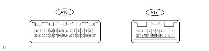
Measure the voltage and the resistance of the wire harness side connector.
| Symbols (Terminals No.) | Wiring Color | Terminal Description | Condition | Specified Condition |
| IG (A17-2) - Body ground | P - Body ground | Ignition switch (on) signal | Ignition switch ON | 10 to 14 V |
| IGS (A17-12) - Body ground | P - Body ground | Ignition switch (on) signal | Ignition switch ON | 10 to 14 V |
| MPX1 (A17-5) - Body ground | P - Body ground | MPX line | Always | 10 kΩ or higher |
| E1 (A17-1) - Body ground | W-B - Body ground | Ground | Always | Below 1 Ω |
| CHECK POSITION CONTROL ECU AND SWITCH ASSEMBLY (W/ DRIVING POSITION MEMORY) |
Disconnect the P30 and P31 ECU connectors.
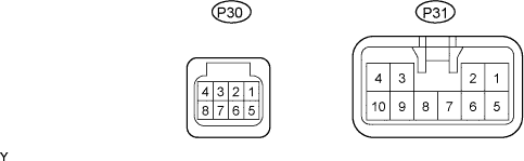
Measure the voltage and the resistance of the wire harness side connector.
| Symbols (Terminals No.) | Wiring Color | Terminal Description | Condition | Specified Condition |
| +B (P31-5) - Body ground | LG - Body ground | +B (+B) power supply | Always | 10 to 14 V |
| MPX1 (P30-1) - Body ground | W - Body ground | MPX line | Always | 10 kΩ or higher |
| GND (P31-1) - Body ground | W-B - Body ground | Ground | Always | Below 1 Ω |
| CHECK AIR CONDITIONING AMPLIFIER (A/C ECU) |
Disconnect the A11 amplifier connector.
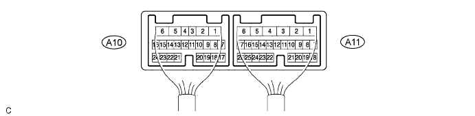
Measure the voltage and resistance of the wire harness side connector.
| Symbols (Terminals No.) | Wiring Color | Terminal Description | Condition | Specified Condition |
| IG+ (A11-1) - Body ground | Y - Body ground | Ignition switch (on) signal | Ignition switch ON | 10 to 14 V |
| MPX+ (A11-3) - Body ground | BR - Body ground | MPX line | Always | 10 kΩ or higher |
| MPX- (A11-4) - Body ground | GR - Body ground | MPX line | Always | 10 kΩ or higher |
| GND (A11-6) - Body ground | W-B - Body ground | Ground | Always | Below 1 Ω |
| CHECK CENTER AIRBAG SENSOR ASSEMBLY |
Disconnect the A24 sensor connector.
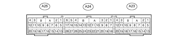
Measure the voltage and resistance of the wire harness side connector.
| Symbols (Terminals No.) | Wiring Color | Terminal Description | Condition | Specified Condition |
| IG2 (A24-5) - Body grond | B - Body grond | Ignition switch (on) signal | Ignition switch ON | 10 to 14 V |
| MPX1 (A24-24) - Body ground | BR - Body ground | MPX line | Always | 10 kΩ or higher |
| MPX2 (A24-22) - Body ground | BR - Body ground | MPX line | Always | 10 kΩ or higher |
| E2 (A24-28) - Body ground | W-B - Body ground | Ground | Always | Below 1 Ω |
| CHECK COMBINATION METER ASSEMBLY (METER ECU) |
Disconnect the C8 and C9 meter connectors.

Measure the voltage and resistance of the wire harness side connector.
| Symbols (Terminals No.) | Wiring Color | Terminal Description | Condition | Specified Condition |
| B (C8-15) - Body ground | SB - Body ground | +B (B) power supply | Always | 10 to 14 V |
| B (C8-16) - Body ground | O - Body ground | +B (B) power supply | Always | 10 to 14 V |
| MPX+ (C9-4) - Body ground | V - Body ground | MPX line | Always | 10 kΩ or higher |
| MPX- (C8-5) - Body ground | Y - Body ground | MPX line | Always | 10 kΩ or higher |
| E (C9-1) - Body ground | W-B - Body ground | Ground | Always | Below 1 Ω |
| CHECK SLIDING ROOF DRIVE GEAR (SLIDING ROOF CONTROL ECU) |
Disconnect the M5 driver gear connector.
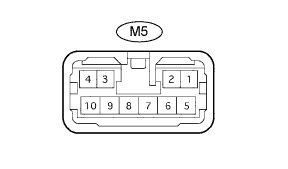
Measure the voltage and the resistance of the wire harness side connector.
| Symbols (Terminals No.) | Wiring Color | Terminal Description | Condition | Specified Condition |
| B (M5-1) - Body ground | P - Body ground | +B (B) power supply | Always | 10 to 14 V |
| MPX1 (M5-10) - Body ground | R - Body ground | MPX line | Always | 10 kΩ or higher |
| E (M5-7) - Body ground | W-B - Body ground | Ground | Always | Below 1 Ω |
| CHECK MULTIPLEX TILT AND TELESCOPIC ECU (W/ DRIVING POSITION MEMORY) |
Disconnect the T4 ECU connector.

Measure the voltage and resistance of the wire harness side connector.
| Symbols (Terminals No.) | Wiring Color | Terminal Description | Condition | Specified Condition |
| +B (T4-2) - Body ground | Y - Body ground | +B (+B) power supply | Always | 10 to 14 V |
| MPX1 (T4-5) - Body ground | GR - Body ground | MPX line | Always | 10 kΩ or higher |
| MPX2 (T4-14) - Body ground | O - Body ground | MPX line | Always | 10 kΩ or higher |
| GND (T4-11) - Body ground | W-B - Body ground | Ground | Always | Below 1 Ω |
| CHECK RAIN SENSOR (W/ AUTOMATIC WIPER SYSTEM) |
Disconnect the R7 sensor connector.

Measure the voltage and resistance of the wire harness side connector.
| Symbols (Terminals No.) | Wiring Color | Terminal Description | Condition | Specified Condition |
| SIG (R7-1) - Body ground | P - Body ground (*1) B - Body ground (*2) | Ignition switch (on) signal | Ignition switch ON | 10 to 14 V |
| MPX (R7-2) - Body ground | V - Body ground | MPX line | Always | 10 kΩ or higher |
| ES (R7-3) - Body ground | W-B - Body ground | Ground | Always | Below 1 Ω |
| CHECK MULTIPLEX NETWORK MASTER SWITCH |
Disconnect the P19 switch connector.

Measure the voltage and resistance of the wire harness side connector.
| Symbols (Terminals No.) | Wiring Color | Terminal Description | Condition | Specified Condition |
| CPUB (P19-9) - Body ground | L-B - Body ground | +B (CPUB) power supply | Always | 10 to 14 V |
| GND (P19-2) - Body ground | W-B - Body ground | Ground | Always | Below 1 Ω |
| MPX1 (P19-7) - Body ground | R - Body ground | MPX line | Always | 10 kΩ or higher |
| MPX2 (P19-8) - Body ground | GR - Body ground | MPX line | Always | 10 kΩ or higher |
| CHECK MULTIPLEX BACK DOOR ECU |
Disconnect the P10 and P11 ECU connectors.
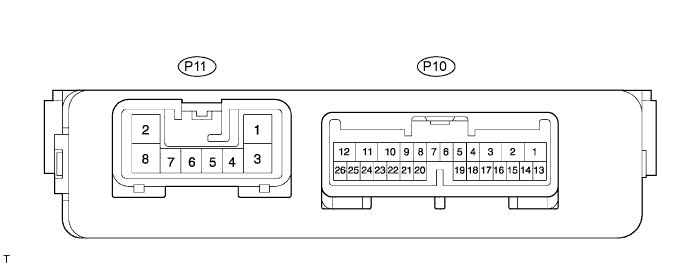
Measure the voltage and resistance of the wire harness side connector.
| Symbols (Terminals No.) | Wiring Color | Terminal Description | Condition | Specified Condition |
| B (P11-2) - Body ground | Y - Body ground | +B (B) power supply | Always | 10 to 14 V |
| MPX1 (P10-22) - Body ground | SB - Body ground | MPX line | Always | 10 kΩ or higher |
| GND (P11-8) - Body ground | W-B - Body ground | Ground | Always | Below 1 Ω |
| CHECK TRANSPONDER KEY ECU |
Disconnect the T8 ECU connector.

Measure the resistance and voltage of the wire harness side connector.
| Symbols (Terminals No.) | Wiring Color | Terminal Description | Condition | Specified Condition |
| CPUB (T8-1) - Body ground | V - Body ground | B (CPUB) power supply | Always | 10 to 14 V |
| MPX1 (T8-4) - Body ground | O - Body ground | MPX line | Always | 10 kΩ or higher |
| MPX2 (T8-5) - Body ground | R - Body ground | MPX line | Always | 10 kΩ or higher |
| GND (T8-14) - Body ground | W-B - Body ground | Ground | Always | Below 1 Ω |
| CHECK OUTER MIRROR CONTROL ECU LH (W/ DRIVING POSITION MEMORY) |
Disconnect the R17 ECU connector.
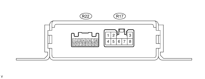
Measure the resistance and voltage of the wire harness side connector.
| Symbols (Terminals No.) | Wiring Color | Terminal Description | Condition | Specified Condition |
| CPUB (R17-7) - Body ground | L-B - Body ground | B (CPUB) power supply | Always | 10 to 14 V |
| MPX1 (R17-6) - Body ground | R - Body ground | MPX line | Always | 10 kΩ or higher |
| GND (R17-1 ) - Body ground | W-B - Body ground | Ground | Always | Below 1 Ω |
| CHECK OUTER MIRROR CONTROL ECU RH |
Disconnect the R18 ECU connector.
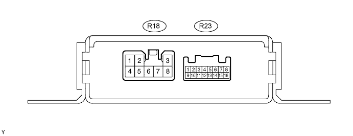
Measure the resistance and voltage of the wire harness side connector.
| Symbols (Terminals No.) | Wiring Color | Terminal Description | Condition | Specified Condition |
| CPUB (R18-7) - Body ground | L-B - Body ground | B (CPUB) power supply | Always | 10 to 14 V |
| MPX1 (R18-6) - Body ground | L - Body ground | MPX line | Always | 10 kΩ or higher |
| GND (R18-1 ) - Body ground | W-B - Body ground | Ground | Always | Below 1 Ω |
| CHECK DOUBLE DOOR LOCK ECU |
Disconnect the D2 ECU connector.

Measure the resistance and voltage of the wire harness side connector.
| Symbols (Terminals No.) | Wiring Color | Terminal Description | Condition | Specified Condition |
| +B (D2-1) - Body ground | R - Body ground | B (+B) power supply | Always | 10 to 14 V |
| MPX1 (D2-9) - Body ground | LG - Body ground | MPX line | Always | 10 kΩ or higher |
| GND (D2-14) - Body ground | W-B - Body ground | Ground | Always | Below 1 Ω |
