CAN COMMUNICATION SYSTEM (for LHD) > Television Camera ECU Communication Stop Mode |
| Detection Item | Symptom | Suspected Area |
| TELEVISION CAMERA ECU COMMUNICATION STOP MODE |
|
|
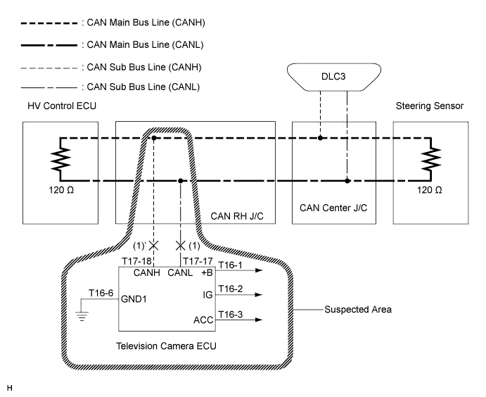
| 1.CHECK CAN BUS LINE FOR DISCONNECTION (TELEVISION CAMERA ECU SUB BUS LINE) |
Turn the ignition switch off.
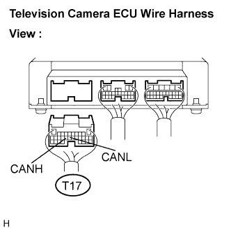 |
Disconnect the television camera ECU connector (T17).
Measure the resistance according to the value(s) in the table below.
| Tester Connection | Condition | Specified Value |
| T17-18 (CANH) - T17-17 (CANL) | Disconnect the negative auxiliary battery cable | 54 to 69 Ω |
|
| ||||
| OK | |
| 2.CHECK WIRE HARNESS (IG, +B, ACC, GND1) |
Reconnect the television camera ECU connector (T17).
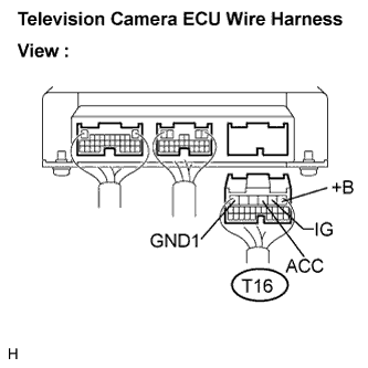 |
Disconnect the television camera ECU connector (T16).
Measure the resistance according to the value(s) in the table below.
| Tester Connection | Condition | Specified Value |
| T16-6 (GND1) - Body ground | Always | Below 1 Ω |
Measure the voltage according to the value(s) in the table below.
| Tester Connection | Condition | Specified Value |
| T16-1 (+B) - Body ground | Always | 10 to 14 V |
| T16-2 (IG) - Body ground | Ignition switch on | 10 to 14 V |
| T16-3 (ACC) - Body ground | Ignition switch ACC | 10 to 14 V |
|
| ||||
| OK | ||
| ||
