POWER DOOR LOCK CONTROL SYSTEM > Driver Side Door UNLOCK Detection Switch Circuit |
| 1.READ VALUE OF DATA LIST (DOOR UNLOCK DETECTION SWITCH) |
Check the DATA LIST to ensure proper operation of the door unlock detection switch.
| Item | Measurement Item / Display (Range) | Normal Condition | Diagnostic Note |
| Door Unlock Detection SW | Door unlock detection switch signal /ON or OFF | ON: Any door is unlocked OFF: All doors are locked | - |
|
| ||||
| OK | ||
| ||
| 2.INSPECT FRONT DOOR LOCK ASSEMBLY (DOOR UNLOCK DETECTION SWITCH) |
LHD Models:
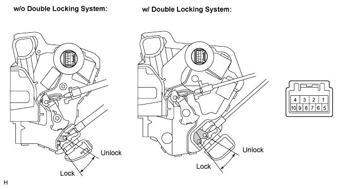
Measure the resistance according to the value(s) in the table below.
| Measurement Condition | Door Lock Condition | Specified Condition |
| Battery positive (+) → Terminal 4 Battery negative (-) → Terminal 3 | Lock | 7 to 8 (10 kΩ or higher) |
| Battery positive (+) → Terminal 3 Battery negative (-) → Terminal 4 | Unlock | 7 to 8 (Below 1 Ω) |
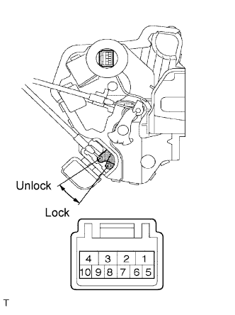 |
RHD Models:
Remove the front door lock assembly RH.
Measure the resistance according to the value(s) in the table below.
| Measurement Condition | Door Lock Condition | Specified Condition |
| Battery positive (+) → Terminal 2 Battery negative (-) → Terminal 1 | Lock | 7 to 8 (10 kΩ or higher) |
| Battery positive (+) → Terminal 1 Battery negative (-) → Terminal 2 | Unlock | 7 to 8 (Below 1 Ω) |
|
| ||||
| OK | |
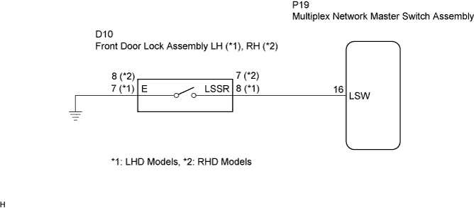
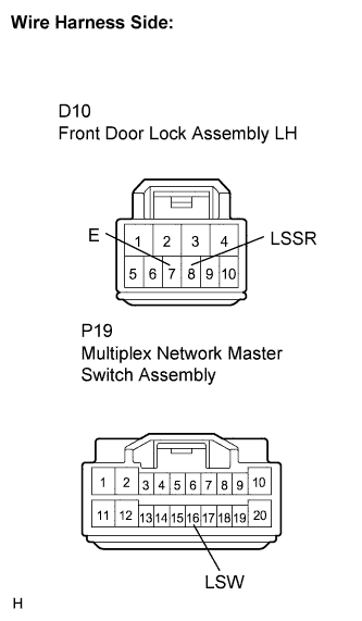
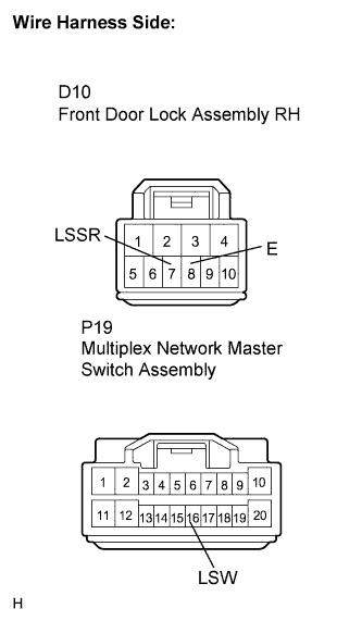
| 3.CHECK WIRE HARNESS (FRONT DOOR LOCK ASSEMBLY - P/W REGULATOR MASTER SWITCH) |
 |
LHD Models:
Disconnect the front door lock assembly connector.
Disconnect the power window regulator master switch assembly connector.
Measure the resistance according to the value(s) in the table below.
| Tester Connection | Condition | Specified Condition |
| D10-8 (LSSR) - P19-16 (LSW) | Always | Below 1 Ω |
| D10-7 (E) - Body ground | Always | Below 1 Ω |
 |
RHD Models:
Disconnect the front door lock assembly connector.
Disconnect the power window regulator master switch assembly connector.
Measure the resistance according to the value(s) in the table below.
| Tester Connection | Condition | Specified Condition |
| D10-7 (LSSR) - P19-16 (LSW) | Always | Below 1 Ω |
| D10-8 (E) - Body ground | Always | Below 1 Ω |
|
| ||||
| OK | ||
| ||
