POWER DOOR LOCK CONTROL SYSTEM > Front Passenger Side Door Lock Motor Circuit |
| 1.INSPECT FRONT DOOR LOCK ASSEMBLY (DOOR LOCK MOTOR) |
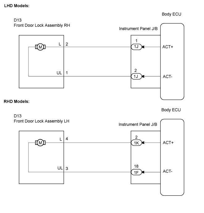
LHD Models:
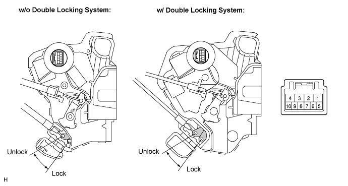
Apply battery voltage and check operation of the door lock motor.
| Measurement Condition | Specified Condition |
| Battery positive (+) → Terminal 2 Battery nagative (-) → Terminal 1 | Lock |
| Battery positive (+) → Terminal 1 Battery nagative (-) → Terminal 2 | Unlock |
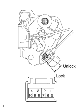 |
RHD Models:
Remove the front door lock assembly LH.
Apply battery voltage and check operation of the door lock motor.
| Measurement Condition | Specified Condition |
| Battery positive (+) → Terminal 4 Battery nagative (-) → Terminal 3 | Lock |
| Battery positive (+) → Terminal 3 Battery nagative (-) → Terminal 4 | Unlock |
|
| ||||
| OK | |
| 2.CHECK WIRE HARNESS (FRONT DOOR LOCK ASSEMBLY - INSTRUMENT PANEL J/B) |
 |
LHD Models:
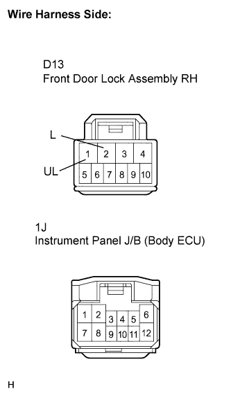
Disconnect the front door lock assembly RH connector.
Disconnect the instrument panel J/B connector.
Measure the resistance according to the value(s) in the table below.
| Tester Connection | Condition | Specified Condition |
| D13-2 (L) - 1J-1 | Always | Below 1 Ω |
| D13-1 (UL) - 1J-2 | Always | Below 1 Ω |
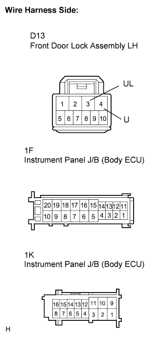 |
RHD Models:
Disconnect the front door lock assembly LH connector.
Disconnect the instrument panel J/B connector.
Measure the resistance according to the value(s) in the table below.
| Tester Connection | Condition | Specified Condition |
| D13-4 (L) - 1K-2 | Always | Below 1 Ω |
| D13-3 (UL) - 1F-18 | Always | Below 1 Ω |
|
| ||||
| OK | ||
| ||
