WINDOW DEFOGGER SYSTEM > Rear Window Defogger System does not Operate |
| 1.INSPECT COMMUNICATION LINE |
Use the intelligent tester to check for normal function of the multiplex communication system.
(ECU unconnected, communication line malfunctioning) Without DTC B1214, B1215 or B 1262 outputs, proceed to A.
(ECU unconnected, communication line malfunctioning) With DTC B1214, B1215 or B 1262 outputs, proceed to B.
|
| ||||
| A | |
| 2.INSPECT FUSE (HEATER, RR-DEF) |
Remove the HEATER fuse from the instrument panel J/B.
Remove the RR-DEF fuse from the FL block.
Check the resistance.
|
| ||||
| OK | |
| 3.PERFORM ACTIVE TEST |
Connect the intelligent tester (with CAN VIN) to the DLC3.
Turn the ignition switch on.
Perform the ACTIVE TEST according to the display on the tester.
| Item | Test Details | Diagnostic Note |
| DEFOGGER RLY-R | Operate rear window defogger OFF/ON | - |
|
| ||||
| OK | |
| 4.CHECK AIR CONDITIONING SYSTEM OPERATE |
|
| ||||
| OK | ||
| ||
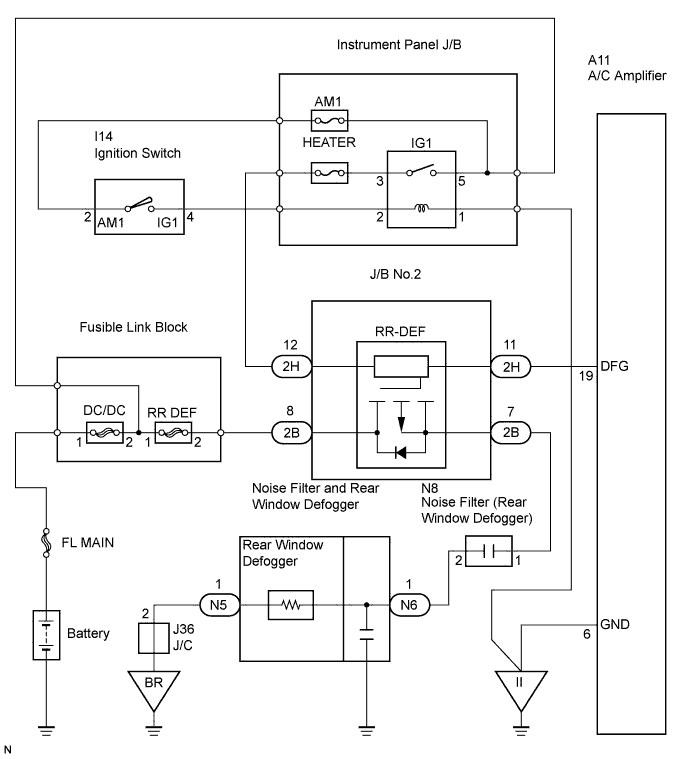
| 5.INSPECT JUNCTION BLOCK |
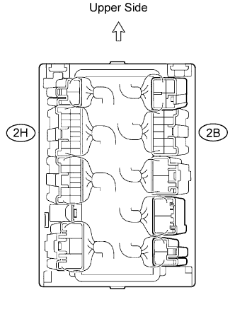 |
Check the voltage of the terminal of the J/B.
| Tester Connection | Switch Position | Specified Condition |
| 2H-12 - Body Ground | Ignition switch ON | 10 to 14 V |
| 2H-12 - Body Ground | Ignition switch OFF | Below 1 V |
| 2B-8 - Body Ground | Always | 10 to 14 V |
|
| ||||
| OK | |
| 6.INSPECT JUNCTION BLOCK (MODE MONITOR TERMINAL) |
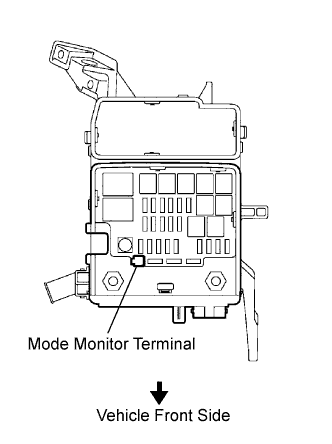 |
Check the voltage of the terminal to the following condition.
| Result | Proceed to |
| More than 5 V | A |
| Below 2 V | B |
|
| ||||
| A | |
| 7.INSPECT JUNCTION BLOCK (RR-DEF RELAY) |
Remove the junction block No.2.
|
Connect the battery positive (+) lead to terminal 2B-8 and battery negative (-) terminal lead to terminal 2H-12, 2B-7 and 2H-11.
Check the voltage of the RR-DEF relay terminals.
| Tester Connection | Condition | Specified Condition |
| 2B-7 - 2H-12 | Always | Below 1 V |
Connect another battery positive (+) lead to the terminal 2H-12.
Check the voltage of the RR-DEF relay terminals.
| Tester Connection | Condition | Specified Condition |
| 2B-7 - 2H-12 | Ignition switch ON | Below 1 V |
| 2B-7 - 2H-12 | Ignition switch OFF | 10 to 14 V |
|
| ||||
| OK | |
| 8.INSPECT AIR CONDITIONING AMPLIFIER ASSEMBLY |
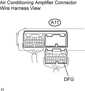 |
Disconnect the A11 connector.
Measure the voltage according to the value(s) in the table below.
| Tester connection | Condition | Specified condition |
| A11-19 (DFG) - Body ground | Ignition switch: ON | 10 to 14 V |
| A11-19 (DFG) - Body ground | Ignition switch: OFF | Below 1 V |
|
| ||||
| OK | |
| 9.INSPECT AIR CONDITIONING AMPLIFIER ASSEMBLY |
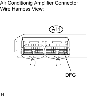 |
Connect the A11 connector.
Connect the intelligent tester to the DLC3.
Measure the voltage according to the value(s) in the table below.
| Tester connection | Intelligent tester condition | Specified condition |
| A11-19 (DFG) - Body ground | ACTIVE TEST: ON (*1) | 10 to 14 V |
| A11-19 (DFG) - Body ground | ACTIVE TEST: OFF (*1) | Below 1 V |
| Item | Test Details | Diagnostic Note |
| DEFOGGER RLY-R | Operate rear window defogger OFF/ON | - |
|
| ||||
| OK | |
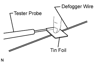
| 10.INSPECT REAR WINDOW DEFOGGER WIRE |
 |
Turn the ignition switch on.
Turn the defogger switch ON.
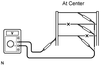 |
Check the voltage at the center of each defogger wire, as shown in the illustration.
| Voltage | Criteria |
| Approx .5 V | Wire is not broken |
| Approx. 10 or 0 V | Wire is broken |
Place the voltmeter positive (+) lead against the defogger wire on the battery side.
Place the voltmeter negative (-) lead with the foil strip against the wire on the ground side.
Slide the positive (+) lead from the battery side to the ground side.
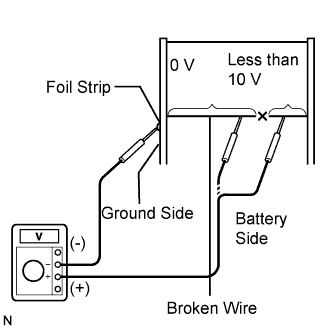 |
The point where the voltage drops from approximately 10 V to 0 V is where the defogger wire is broken.
|
| ||||
| OK | |
| 11.CHECK WIRE HARNESS (REAR WINDOW DEFOGGER - JUNCTION BLOCK NO.2) |
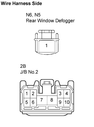 |
Disconnect the N6, N5 defogger and 2B J/B connectors.
Check the resistance of the wire harness side connectors.
| Tester Connection | Specified Condition |
| N6-1 - 2B-7 | Below 1 Ω |
| N6-1 -Body ground | 10 kΩ or higher |
| N5-1 - Body ground | Below 1 Ω |
| N5-1 - 2B-7 | 10 kΩ or higher |
|
| ||||
| OK | ||
| ||
| 12.CHECK WIRE HARNESS (REAR WINDOW DEFOGGER - JUNCTION BLOCK NO.2) |
|
Disconnect the N6, N5 defogger and 2B J/B connectors.
Check the resistance of the wire harness side connectors.
| Tester Connection | Specified Condition |
| N6-1 - 2B-7 | Below 1 Ω |
| N6-1 -Body ground | 10 kΩ or higher |
| N5-1 - Body ground | Below 1 Ω |
| N5-1 - 2B-7 | 10 kΩ or higher |
|
| ||||
| OK | |
| 13.INSPECT JUNCTION BLOCK (RR-DEF RELAY) |
Remove the junction block No.2.
|
Connect the battery positive (+) lead to terminal 2B-8 and battery negative (-) terminal lead to terminal 2H-12, 2B-7 and 2H-11.
Check the voltage of the RR-DEF relay terminals.
| Tester Connection | Condition | Specified Condition |
| 2B-7 - 2H-12 | Always | Below 1 V |
Connect another battery positive (+) lead to the terminal 2H-12.
Check the voltage of the RR-DEF relay terminals.
| Tester Connection | Condition | Specified Condition |
| 2B-7 - 2H-12 | Ignition switch ON | 10 to 14 V |
| 2B-7 - 2H-12 | Ignition switch OFF | Below 1 V |
|
| ||||
| OK | ||
| ||
