REAR CIRCUIT BREAKER SENSOR > REMOVAL |
| 1. DISCONNECT CABLE FROM BATTERY NEGATIVE TERMINAL |
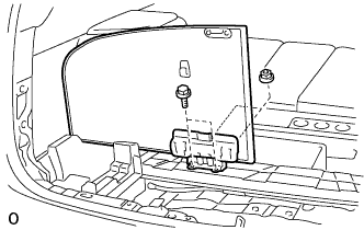
| 2. REMOVE DECK BOARD SUB-ASSEMBLY |
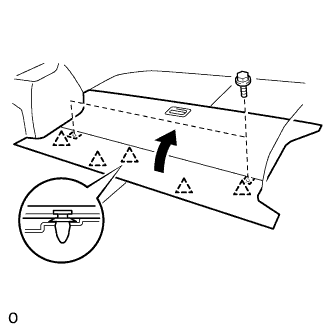 |
Disengage the 5 clips and turn up the front side of the deck board.
Remove the 2 bolts and deck board sub-assembly.
| 3. REMOVE DECK FLOOR BOX REAR |
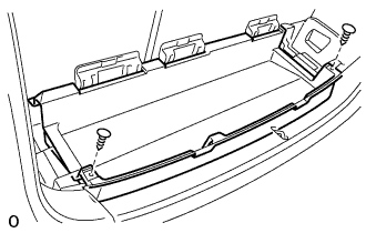 |
Using a clip remover, remove the 2 clips and deck floor box rear.
| 4. REMOVE REAR FLOOR FINISH PLATE |
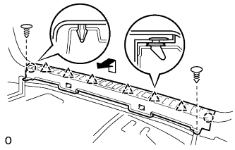 |
Using a clip remover, remove the 2 clips.
Disengage the 2 claws and 6 clips, and remove the rear floor finish plate.
| 5. REMOVE DECK FLOOR BOX FRONT |
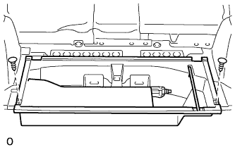 |
Using a clip remover, remove the 2 clips and deck floor box front.
| 6. REMOVE DECK BOARD SUB-ASSEMBLY NO.2 |
 |
Remove the 4 blots, 2 nuts and deck No.2 board sub-assembly.
| 7. REMOVE DECK BOARD SUB-ASSEMBLY NO.3 |
 |
Remove the 2 bolts, 2 nuts and deck No.3 board sub-assembly.
| 8. REMOVE DECK SIDE TRIM BOX RH |
| 9. REMOVE DECK SIDE TRIM BOX LH |
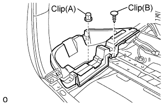 |
Remove the clip (A).
Using a clip remover, remove the clip (B) and deck side trim box.
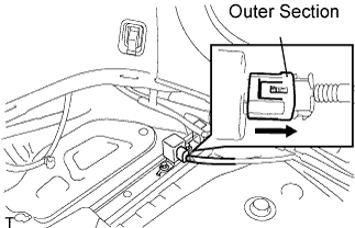
| 10. REMOVE REAR CIRCUIT BREAKER SENSOR |
Remove the rear circuit breaker sensor (LH).
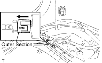 |
Move the outer section to the wire harness side as illustrated, then disconnect the rear circuit breaker sensor (LH).
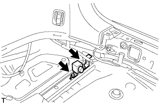
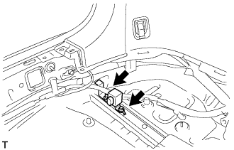 |
Remove the 2 bolts and rear circuit breaker sensor (LH).
Remove the rear circuit breaker sensor (RH).
 |
Move the outer section to the wire harness side as illustrated, then disconnect the rear circuit breaker sensor (RH).
 |
Remove the 2 bolts and rear circuit breaker sensor (RH).
