SFI SYSTEM > ECM Power Source Circuit |
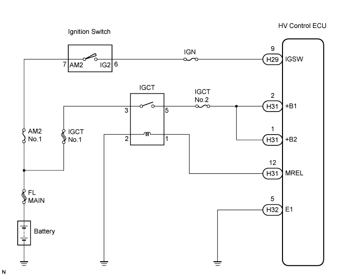
| 1.INSPECT HV CONTROL ECU (+B, +B1 VOLTAGE) |
 |
Turn the ignition switch ON.
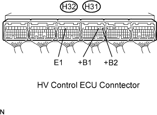
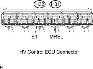
Measure the voltage between the terminals of the H31 and H32 HV Control ECU connectors.
| Tester Connection | Specified Condition |
| +B1 (H31-2) - E1 (H32-5) | 9 to 14 V |
| +B2 (H31-1) - E1 (H32-5) | 9 to 14 V |
|
| ||||
| NG | |
| 2.CHECK HARNESS AND CONNECTOR (HV CONTROL ECU - BODY GROUND) |
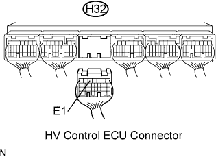 |
Disconnect the H32 HV Control ECU connector.
Measure the resistance between the HV Control ECU and body ground.
| Tester Connection | Specified Condition |
| E1 (H32-5) - Body ground | Below 1 Ω |
Reconnect the HV Control ECU connector.
|
| ||||
| OK | |
| 3.INSPECT HV CONTROL ECU (IGSW VOLTAGE) |
 |
Turn the ignition switch ON.
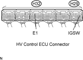
Measure the voltage between the terminals of the H29 and H32 HV Control ECU connectors.
| Tester Connection | Specified Condition |
| IGSW (H29-9) - E1 (H32-5) | 9 to 14 V |
|
| ||||
| NG | |
| 4.CHECK FUSE (IGN FUSE) |
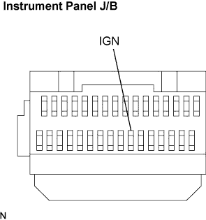 |
Remove the IGN fuse from the instrument panel J/B.
Measure the IGN fuse resistance.
Reinstall the IGN fuse.
|
| ||||
| OK | |
| 5.INSPECT IGNITION SWITCH ASSEMBLY |
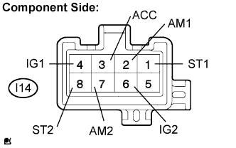 |
Check for continuity between the connector terminals shown in the chart below.
| Switch | Terminal No. | Resistance |
| LOCK | All Terminals | No continuity |
| ACC | 1 - 2 | Continuity |
| ON | 2 - 3, 2 - 4, 3 - 4, 6 - 7 | Continuity |
| START | 1 - 2, 1 - 4, 2 - 4, 6 - 7, 6 - 8, 7 - 8 | Continuity |
|
| ||||
| OK | ||
| ||
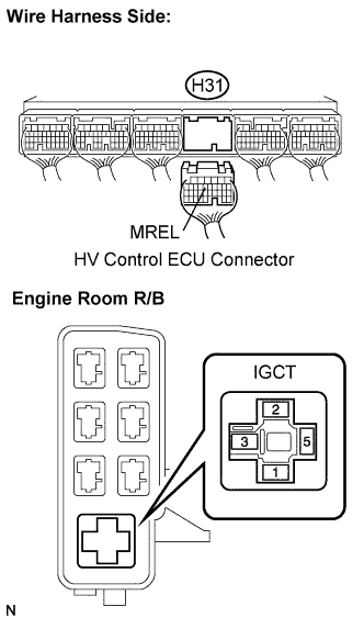
| 6.INSPECT HV CONTROL ECU (MREL VOLTAGE) |
 |
Turn the ignition switch ON.
Measure the voltage between the terminals of the H31 and H32 HV Control ECU connectors.
| Tester Connection | Specified Condition |
| MREL (H31-12) - E1 (H32-5) | 9 to 14 V |
|
| ||||
| OK | |
| 7.CHECK FUSE (IGCT NO.2 FUSE) |
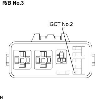 |
Remove the IGCT No.2 fuse from the R/B No.3.
Measure the IGCT No.2 fuse resistance.
Reinstall the IGCT No.2 fuse.
|
| ||||
| OK | |
| 8.INSPECT IGCT RELAY |
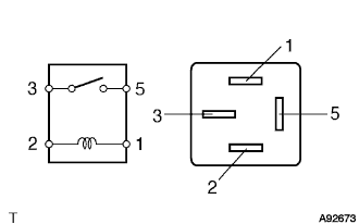 |
Remove the integration relay from the engine room R/B.
Measure the IGCT relay resistance.
| Tester Connection | Specified Condition |
| 3 - 5 | 10 kΩ or higher |
| Below 1 Ω (Apply battery voltage between terminals 1 and 2) |
|
| ||||
| OK | |
| 9.CHECK HARNESS AND CONNECTOR (IGCT RELAY- HV CONTROL ECU, IGCT RELAY - BODY GROUND) |
 |
Check the harness and the connectors between the integration relay and the HV Control ECU.
Remove the IGCT relay from the engine room R/B.
Disconnect the H31 HV Control ECU connector.
Measure the resistance between the wire harness side connectors.
| Tester Connection | Specified Condition |
| IGCT relay (1)- MREL (H31-12) | Below 1 Ω |
| Tester Connection | Specified Condition |
| IGCT relay (1) or MREL (H31-12) - Body ground | 10 kΩ or higher |
Check the harness and the connectors between the integration relay and body ground.
Remove the integration relay from the engine room R/B.
Measure the resistance between the wire harness side connector and body ground.
| Tester Connection | Specified condition |
| IGCT relay (2) - Body ground | Below 1 Ω |
|
| ||||
| OK | ||
| ||
