DTC B1206 P/W Master Switch Communication Stop |
| DTC No. | DTC Detection Condition | Trouble Area |
| B1206 | Multiplex network master switch communication stops |
|
| 1.CHECK OPERATION |
Turn the ignition switch on.
Check that the driver side power window can be operated using the multiplex network master switch.
|
| ||||
| NG | |
| 2.INSPECT FUSE (ECU-B No.1) |
Remove the ECU-B No.1 fuse from the fusible link block.
Measure the resistance of the fuse.
|
| ||||
| OK | |
| 3.CHECK WIRE HARNESS (MULTIPLEX NETWORK MASTER SWITCH - BATTERY AND BODY GROUND) |
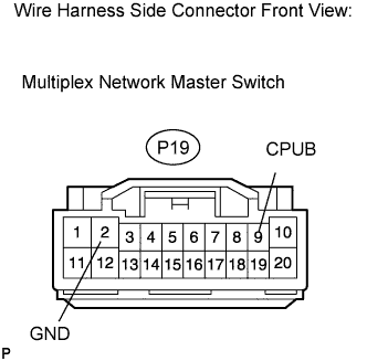 |
Disconnect the P19 switch connector.
Measure the voltage of the wire harness side connector.
| Tester Connection | Specified Connection |
| P19-9 (CPUB) - Body ground | 10 to 14 V |
Measure the resistance of the wire harness side connector.
| Tester Connection | Specified Connection |
| P19-2 (GND) - Body ground | Below 1 Ω |
|
| ||||
| OK | |
| 4.CHECK RESISTANCE OF COMMUNICATION LINE |
Disconnect the G1 ECU connector (w/o Driving position memory).
Disconnect the T4 ECU connector (w/ Driving position memory).
Disconnect the 1E instrument panel connector.
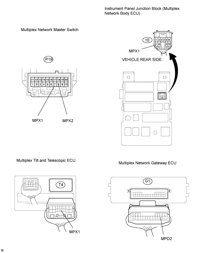
Measure the resistance of the wire harness side connectors.
| Tester Connection | Specified Condition |
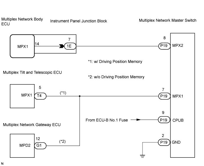
| P19-8 (MPX2) - 1E-7 (MPX1) | Below 1 Ω |
| P19-7 (MPX1) - T4-5 (MPX1) (*1) | Below 1 Ω |
| P19-7 (MPX1) - G1-12 (MPD2) (*2) | Below 1 Ω |
|
| ||||
| OK | ||
| ||
