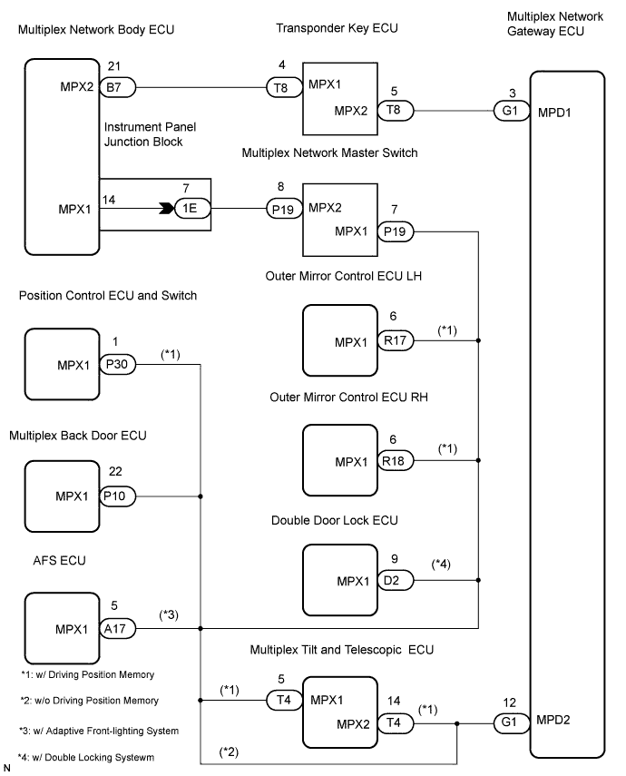
DTC B1214 Door System Communication Bus Malfunction (+B Short) |
DTC B1215 Door System Communication Bus Malfunction (GND Short) |
| DTC No. | DTC Detection Condition | Trouble Area |
| B1214 | Door system communication circuit and +B battery system short |
|
| B1215 | Door system communication circuit and body ground short |
|
| 1.CHECK APPARATUS |
Choose the apparatus to be inspected.
| Apparatus | Go to step |
| w/ Driving position memory | A |
| w/o Driving position memory | B |
|
| ||||
| A | |
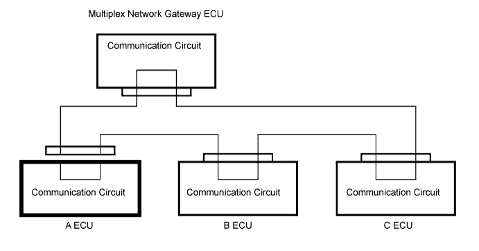
| 2.CHECK DIAGNOSTIC TROUBLE CODE (A ECU) |
Disconnect the A ECU connector and check for DTCs B1214 and B1215.
|
| ||||
| NG | |
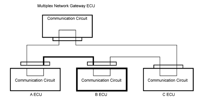
| 3.CHECK DIAGNOSTIC TROUBLE CODE (B ECU) |
Disconnect the A ECU and B ECU connectors and check for DTCs B1214 and B1215.
|
| ||||
| OK | |
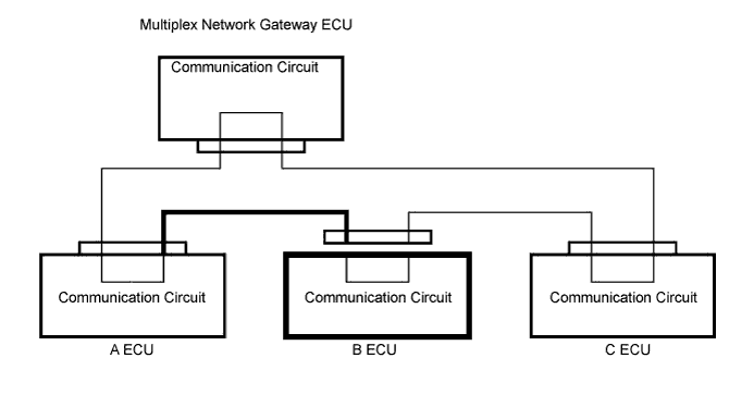
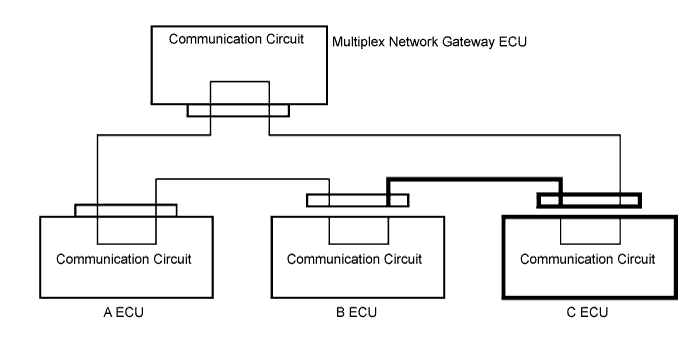
| 4.CHECK WIRE HARNESS BETWEEN A ECU AND B ECU |
Disconnect the B ECU connector and check for DTCs B1214 and B1215.
|
| ||||
| OK | ||
| ||
| 5.CHECK DIAGNOSTIC TROUBLE CODE (C ECU) |
Disconnect the B ECU and C ECU connectors and check for DTCs B1214 and B1215.
|
| ||||
| OK | |
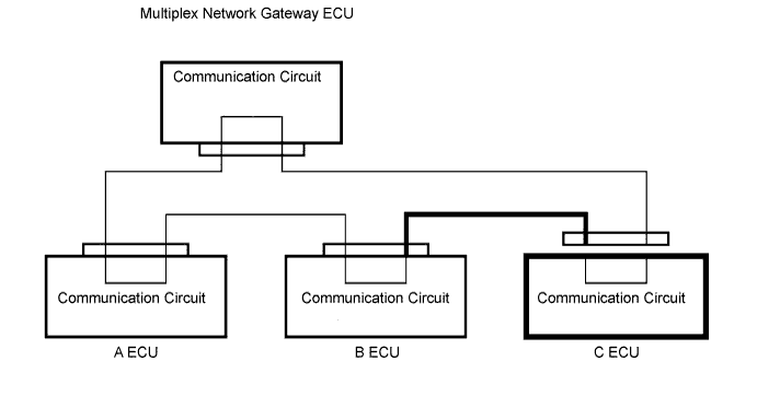
| 6.CHECK WIRE HARNESS BETWEEN B ECU AND C ECU |
Disconnect the C ECU connector and check for DTCs B1214 and B1215.
|
| ||||
| OK | ||
| ||
| 7.CHECK WIRE HARNESS BETWEEN NETWORK GATEWAY ECU AND A ECU OR C ECU |
Check for a short-circuit in B+ or body ground.
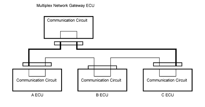
Disconnect the A ECU, C ECU and multiplex network gateway ECU connectors.
Measure the voltage and resistance of the wire harness side connectors.
| Tester Connection | Specified Condition |
| A ECU connector/multiplex network gateway ECU connector - Body ground | Below 1 V |
| C ECU connector/multiplex network gateway ECU connector - Body ground | Below 1 V |
| Tester Connection | Specified Condition |
| A ECU connector / multiplex network gateway ECU connector - Body ground | 10 kΩ or higher |
| C ECU connector / multiplex network gateway ECU connector - Body ground | 10 kΩ or higher |
|
| ||||
| OK | ||
| ||
| 8.CHECK DIAGNOSTIC TROUBLE CODE (BACK DOOR ECU) |
Disconnect the multiplex back door ECU connector and check for DTCs B1214 and B1215.
|
| ||||
| NG | |
| 9.CHECK DIAGNOSTIC TROUBLE CODE (A ECU) |
Disconnect the A ECU connector and check for DTCs B1214 and B1215.
|
| ||||
| NG | |
| 10.CHECK DIAGNOSTIC TROUBLE CODE (B ECU) |
Disconnect the A ECU and B ECU connectors and check for DTCs B1214 and B1215.
|
| ||||
| OK | |
| 11.CHECK WIRE HARNESS BETWEEN A ECU AND B ECU |
Disconnect the B ECU connector and check for DTCs B1214 and B1215.
|
| ||||
| OK | ||
| ||
| 12.CHECK DIAGNOSTIC TROUBLE CODE (C ECU) |
Disconnect the B ECU and C ECU connectors and check for DTCs B1214 and B1215.
|
| ||||
| OK | |
| 13.CHECK WIRE HARNESS BETWEEN B ECU AND C ECU |
Disconnect the C ECU connector and check for DTCs B1214 and B1215.
|
| ||||
| OK | ||
| ||
| 14.CHECK WIRE HARNESS BETWEEN NETWORK GATEWAY ECU AND A ECU OR C ECU |
Check for a short-circuit in B+ or body ground.
Disconnect the A ECU, C ECU and multiplex network gateway ECU connectors.
Measure the voltage and resistance of the wire harness side connectors.
| Tester Connection | Specified Condition |
| A ECU connector /multiplex network gateway ECU connector - Body ground | Below 1 V |
| C ECU connector /multiplex network gateway ECU connector - Body ground | Below 1 V |
| Tester Connection | Specified Condition |
| A ECU connector / multiplex network gateway ECU connector - Body ground | 10 kΩ or higher |
| C ECU connector / multiplex network gateway ECU connector - Body ground | 10 kΩ or higher |
|
| ||||
| OK | ||
| ||
