DTC B1272 Power Seat ECU Communication Stop |
| DTC No. | DTC Detection Condition | Trouble Area |
| B1272 | Position control ECU and switch assembly (driver seat ECU) communication stops |
|
| 1.CHECK OPERATION |
Check that the switch of the front power seat can move the driver side seat normally.
|
| ||||
| NG | |
| 2.INSPECT FUSE (P/SEAT) |
Remove the P/SEAT fuse from the instrument panel junction block.
Measure the resistance of the fuse.
|
| ||||
| OK | |
| 3.CHECK WIRE HARNESS (POSITION CONTROL ECU AND SWITCH ASSEMBLY (DRIVER SEAT ECU) - BATTERY AND BODY GROUND) |
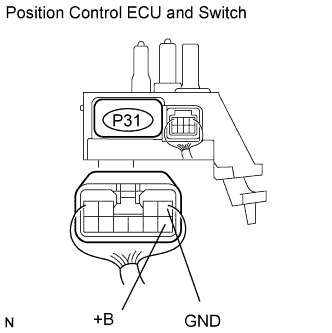 |
Disconnect the P31 ECU connector.
Measure the resistance and voltage of the wire harness side connector.
| Tester Connection | Specified Condition |
| P31-5 (+B) - Body ground | 10 to 14 V |
| Tester Connection | Specified Condition |
| P31-1 (GND) - Body ground | Below 1 Ω |
|
| ||||
| OK | |
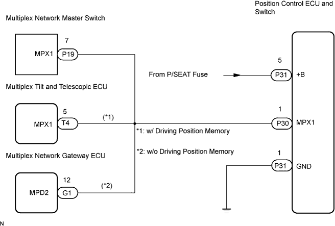
| 4.CHECK RESISTANCE OF COMMUNICATION LINE |
Disconnect the P30, P19 and T4 ECU connectors (w/ Driving position memory).
Disconnect the P30, P19 and G3 ECU connectors (w/o Driving position memory).
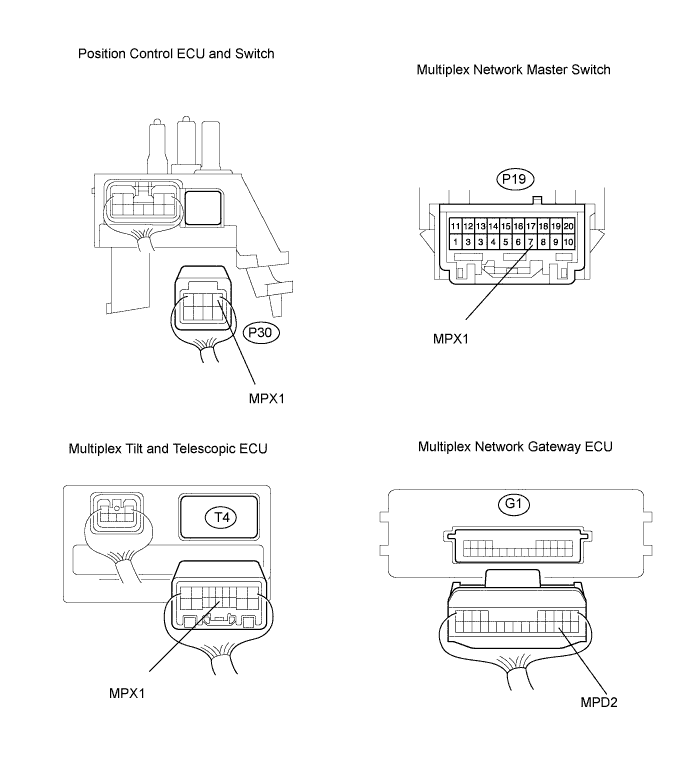
Measure the resistance of the wire harness side connectors.
| Tester Connection | Specified Condition |
| P30-1 (MPX1) - T4-5 (MPX1) (*1) | Below 1 Ω |
| P30-1 (MPX1) - P19-7 (MPX1) | Below 1 Ω |
| P30-1 (MPX1) - G1-12 (MPD2) (*2) | Below 1 Ω |
|
| ||||
| OK | ||
| ||
