DTC P3233-750 Short to B+ in Blocking of HV Gate Connection |
| DTC No. | INF Code | DTC Detection Condition | Trouble Area |
| P3233 | 750 | Open or +B short in emergency shutdown signal circuit |
|
| 1.CHECK HARNESS AND CONNECTOR (HV CONTROL ECU - MG ECU) |
Turn the ignition switch off and remove the service plug grip. (Click here)
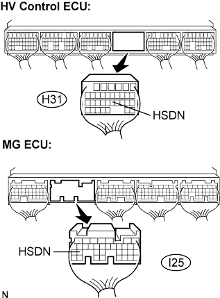 |
Disconnect the H31 connector from the HV control ECU.
Remove the inverter cover. (Click here)
Disconnect the I25 connector from the w/ converter inverter assembly (MG ECU).
Measure the voltage according to the value(s) in the table below when the ignition switch is in the ON position.
| Tester Connection | Specified Condition |
| HSND (H31-21) - Body ground | Below 1 V |
Turn the ignition switch off.
Measure the resistance according to the value(s) in the table below.
| Tester Connection HV ECU - MG ECU | Specified Condition |
| HSDN (H31-21) - HSDN (I25-26) | Below 1 Ω |
|
| ||||
| OK | |
| 2.CHECK W/ CONVERTER INVERTER ASSEMBLY |
 |
Measure the resistance according to the value(s) in the table below.
| Tester Connection | Specified Condition |
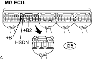
| HSDN (I25-26) - +B (I25-7) | 10 kΩ or higher |
| HSDN (I25-26) - +B (I25-4) | 10 kΩ or higher |
|
| ||||
| OK | ||
| ||
