ELECTRONICALLY CONTROLLED BRAKE SYSTEM > TERMINALS OF ECU |
| CHECK BATTERY VOLTAGE |
Measure the battery voltage.
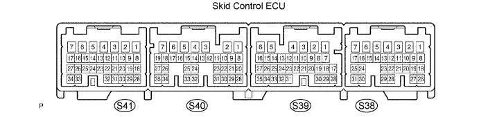
| SKID CONTROL ECU ASSEMBLY INSPECTION |
Measure the voltage between each terminal or between each terminal and the body ground.
Connect the intelligent tester to the DCL3, and check the communication condition with the skid control ECU.
Using an oscilloscope, check that the pulse generates between each terminal or between each terminal and the body ground.
| Symbols (Terminal No.) | Wiring Color | Terminal Description | Condition | Specified Condition |
| GND1 (S41-1) - Body ground | W-B - Body ground | Skid control ECU ground | Always | Below 1 Ω |
| R1+ (S41-2) - Body ground | P - Body ground | Main relay power 1 | IG switch on | 9.1 to 13.6 V |
| BS1 (S41-3) - Body ground | B - Body ground | Battery source 1 | IG switch ON Approx. 1.5 sec. after pushing IG switch ON | 8.8 to 14 V |
| SMC1 (S41-4) - Body ground | Y - Body ground | Master cut solenoid 1 output | IG switch ON Brake pedal depressed approx. 1.5 sec. after pushing IG switch ON | Below 1.5 V |
| +BCTY (S41-5) - Body ground | V - Body ground | Courtesy power input | Driver door open → close | Approx. 5 sec. 8 to 16 V → Below 1 V |
| SLAFR- (S41-6) - Body ground | W - Body ground | FR solenoid (-) output | IG switch ON Approx. 1.5 sec. after pushing IG switch ON | Below 1.5 Ω |
| SLAFR+ (S41-7) - Body ground | R - Body ground | FR solenoid (+) output | IG switch ON Brake pedal depressed approx. 1.5 sec. after pushing IG switch ON | Pulse generation (see waveform 1) |
| E (S41-8) - Body ground | L - Body ground | Pressure sensor ground | IG switch OFF | Below 1 Ω |
| VCM1 (S41-9) - Body ground | P - Body ground | Pressure sensor power | IG switch ON | 4.75 to 5.25 V |
| MR1+ (S41-11) - Body ground | GR - Body ground | Motor relay power 1 | IG switch ON Approx. 1.5 sec. after pushing IG switch ON | 8.8 to 14 V |
| SR1 (S41-12) - Body ground | L - Body ground | Main relay output 1 | IG switch ON Approx. 1.5 sec. or more after pushing IG switch ON | Below 1 V |
| SCSS (S41-13) - Body ground | BR - Body ground | Stroke simulator cut | IG switch ON Brake pedal depressed | Below 1.5 V |
| SLARL+ (S41-15) - Body ground | L - Body ground | RL solenoid (+) output | IG switch ON Brake pedal depressed approx. 1.5 sec. after pushing IG switch ON | Pulse generation (see waveform 1) |
| SLRRL+ (S41-16) - Body ground | W - Body ground | RL solenoid (+) output | IG switch ON Brake pedal depressed approx. 1.5 sec. after pushing IG switch ON | Pulse generation (see waveform 1) |
| SLRFR+ (S41-17) - Body ground | Y - Body ground | FR solenoid (+) output | IG switch ON After approx. 1.5 sec., brake pedal depressed → released | Pulse generation (see waveform 2) |
| PRL (S41-18) - Body ground | G - Body ground | RL pressure sensor input | IG switch ON Brake pedal released | 0.3 to 0.8 V |
| SG1 (S41-20) - Body ground | BR - Body ground | Pressure sensor shield ground 1 | IG switch OFF | Below 1 Ω |
| PACC (S41-21) - Body ground | W - Body ground | Accumulator pressure sensor input | IG switch ON After pump motor operates and stops by pedal operation | 3.3 to 4.7 V |
| FR (S41-22) - Body ground | L - Body ground | FR sensor (-) input | IG switch OFF | Below 1 Ω |
| PFR (S41-23) - Body ground | Y - Body ground | FR pressure sensor input | IG switch ON Brake pedal released | 0.3 to 0.8 V |
| MR1 (S41-25) - Body ground | L - Body ground | Motor relay output 1 | IG switch ON Pump motor is operating | Below 1.5 V |
| SLRRL- (S41-26) - Body ground | P - Body ground | RL solenoid (-) output | IG switch ON Approx. 1.5 sec. after pushing IG switch ON | Below 1.5 V |
| SLARL- (S41-27) - Body ground | LG - Body ground | RL solenoid (-) output | IG switch ON Approx. 1.5 sec. after pushing IG switch ON | Below 1.5 V |
| MTT (S41-29) - Body ground | R - Body ground | Motor test input | IG switch ON Pump motor is operating | 3.5 V or higher |
| PMC1 (S41-30) - Body ground | R - Body ground | Master pressure sensor input 1 | IG switch ON Brake pedal released | 0.3 to 0.8 V |
| PCK1 (S41-31) - Body ground | B - Body ground | Pressure sensor check output 1 | IG switch ON Approx. 1.5 sec. after pushing IG switch ON | 4.75 to 5.25 V |
| FR+ (S41-32) - Body ground | P - Body ground | FR sensor (+) input | Vehicle speed input | Pulse generation (see waveform 3) |
| SLRFR- (S41-34) - Body ground | B - Body ground | FR solenoid (-) output | IG switch ON Approx. 1.5 sec. after pushing IG switch ON | Below 1.5 V |
| GND3 (S40-1) - Body ground | W-B - Body ground | Skid control ECU ground | Always | Below 1 Ω |
| GND2 (S40-2) - Body ground | W-B - Body ground | Skid control ECU ground | Always | Below 1 Ω |
| +BI1 (S40-3) - Body ground | B - Body ground | Main relay power input 1 | IG switch OFF | 10 to 14 V |
| WFSE (S40-4) - Body ground | GR - Body ground | Mode control signal input | IG switch ON | 9.1 to 13.6 V |
| +BO1 (S40-5) - Body ground | Y - Body ground | Main relay power output 1 | IG switch ON | 8.8 to 14 V |
| IG1 (S40-7) - Body ground | B - Body ground | IG1 power | IG switch ON | 10 to 14 V |
| RRS (S40-10) - Body ground | BR - Body ground | Speed sensor shield ground | IG switch OFF | Below 1 Ω |
| BZ (S40-12) - Body ground | BR - Body ground | Warning buzzer output | IG switch ON Buzzer is operating | Below 1 V |
| STP (S40-14) - Body ground | R - Body ground | Stop light switch signal input | IG switch ON Brake pedal depressed → released | 10 to 12 V → Below 1.5 V |
| CAN-L (S40-18) - Body ground | W - Body ground | CAN communication (Send and receive-) | Check DTC using intelligent tester | CAN communication's DTC is not output |
| CAN-H (S40-19) - Body ground | B - Body ground | CAN communication (Send and receive+) | Check DTC using intelligent tester | CAN communication's DTC is not output |
| FAIL (S40-20) - Body ground | P - Body ground | Capacitor communication (Receive) | IG switch ON Approx. 1.5 sec. after pushing IG switch ON | Pulse generation (see waveform 5) |
| SP1 (S40-22) - Body ground | V - Body ground | Speedometer output | Vehicle speed input | Pulse generation (see waveform 4) |
| RLO (S40-25) - Body ground | P - Body ground | RL speed signal output | Vehicle speed output | Pulse generation (see waveform 7) |
| RL- (S40-27) - Body ground | B - Body ground | RL sensor (-) input | IG switch OFF | Below 1 Ω |
| D/G (S40-28) - Body ground | W - Body ground | Diagnosis output | IG switch ON | 9.1 to 13.6 V |
| ENA (S40-30) - Body ground | B - Body ground | Capacitor communication (Send) | IG switch ON Approx. 1.5 sec. after pushing IG switch ON | Pulse generation (see waveform 6) |
| TS (S40-32) - Body ground | L - Body ground | Sensor diagnosis check input | IG switch ON | Below 1.5 V → 9.1 to 13.6 V |
| VBZ (S40-33) - Body ground | B - Body ground | Warning buzzer power | IG switch ON | 9.1 to 13.6 V |
| RL+ (S40-35) - Body ground | W - Body ground | RL sensor (+) input | Vehicle speed input | Pulse generation (see waveform 3) |
| GND5 (S39-1) - Body ground | W-B - Body ground | Skid control ECU ground | Always | Below 1 Ω |
| GND4 (S39-2) - Body ground | W-B - Body ground | Skid control ECU ground | Always | Below 1 Ω |
| +BO2 (S39-4) - Body ground | W - Body ground | Main relay power output 2 | IG switch ON | 8.8 to 14 V |
| +BI2 (S39-5) - Body ground | R - Body ground | Main relay power input 2 | IG switch OFF | 10 to 14 V |
| VCSK (S39-6) - Body ground | B - Body ground | Stroke sensor power | IG switch ON | 3.75 to 4.95 V |
| SSK (S39-7) - Body ground | Shielded - Body ground | Stroke sensor shield ground | IG switch OFF | Below 1 Ω |
| SKG (S39-8) - Body ground | W - Body ground | Stroke sensor power | IG switch OFF | Below 1 Ω |
| PKB (S39-14) - Body ground | R - Body ground | Parking brake signal input | Parking brake applied → released | Below 1.5 V → 9.1 to 13.6 V |
| SKS1 (S39-21) - Body ground | R - Body ground | Stroke sensor signal input 1 | IG switch ON Brake pedal released | 0.46 to 1.35 V |
| SKS2 (S39-22) - Body ground | G - Body ground | Stroke sensor signal input 2 | IG switch ON Brake pedal released | 2.56 to 4.35 V |
| RR- (S39-23) - Body ground | B - Body ground | RR sensor (-) input | IG switch OFF | Below 1 Ω |
| EXI (S39-24) - Body ground | G - Body ground | Cruise relay ON signal input | Cruise control brake OFF → ON | Below 1 Ω → 10 to 14 V |
| RR+ (S39-31) - Body ground | W - Body ground | RR sensor (+) input | Vehicle speed input | Pulse generation (see waveform 3) |
| RRO (S39-33) - Body ground | O - Body ground | RR speed signal output | Vehicle speed output | Pulse generation (see waveform 7) |
| SLAFL+ (S38-1) - Body ground | P - Body ground | FL solenoid (+) output | IG switch ON Brake pedal depressed approx. 1.5 sec. after pushing IG switch ON | Pulse generation (see waveform 1) |
| SLAFL- (S38-2) - Body ground | O - Body ground | FL solenoid (-) output | IG switch ON Approx. 1.5 sec. after pushing IG switch ON | Below 1.5 V |
| SMC2 (S38-3) - Body ground | LG - Body ground | Master cut solenoid 2 output | IG switch ON Brake pedal depressed approx. 1.5 sec. after pushing IG switch ON | Below 1.5 V |
| IG2 (S38-5) - Body ground | O - Body ground | IG2 power | IG switch ON | 10 to 14 V |
| LBL (S38-6) - Body ground | P - Body ground | Brake fluid level switch input | Reservoir level switch OFF → ON | 4 to 4.65 V → Below 1.5 V |
| BS2 (S38-7) - Body ground | P - Body ground | Battery source 2 | IG switch ON Approx. 1.5 sec. after pushing IG switch ON | 8.8 to 14 V |
| SLRFL+ (S38-8) - Body ground | Y - Body ground | FL solenoid (+) output | IG switch ON After approx. 1.5 sec., brake pedal depressed → released | Pulse generation (see waveform 2) |
| SLARR- (S38-9) - Body ground | P - Body ground | RR solenoid (-) output | IG switch ON Approx. 1.5 sec. after pushing IG switch ON | Below 1.5 V |
| CR (S38-11) - Body ground | G - Body ground | Cruise relay output | Cruise control brake OFF → ON | Below 1 V → 10 to 14 V |
| SG2 (S38-12) - Body ground | Shielded - Body ground | Pressure sensor shield ground 2 | IG switch OFF | Below 1 Ω |
| FSS (S38-13) - Body ground | BR - Body ground | Speed sensor shield ground | IG switch OFF | Below 1 Ω |
| VCM2 (S38-14) - Body ground | B - Body ground | Pressure sensor power 2 | IG switch ON | 4.75 to 5.25 V |
| SR2 (S38-15) - Body ground | V - Body ground | Main relay output 2 | IG switch ON Approx. 1.5 sec. after pushing IG switch ON | Below 1 V |
| R2+ (S38-17) - Body ground | Y - Body ground | Main relay power 2 | IG switch ON | 9.1 to 13.6 V |
| SLRRR- (S38-18) - Body ground | BR - Body ground | RR solenoid (-) output | IG switch ON Approx. 1.5 sec. after pushing IG switch ON | Below 1.5 V |
| SLARR+ (S38-19) - Body ground | V - Body ground | RR solenoid (+) output | IG switch ON Brake pedal depressed approx. 1.5 sec. after pushing IG switch ON | Pulse generation (see waveform 1) |
| SLRRR+ (S38-20) - Body ground | R - Body ground | RR solenoid (+) output | IG switch ON Brake pedal depressed approx. 1.5 sec. after pushing IG switch ON | Pulse generation (see waveform 1) |
| PCK2 (S38-21) - Body ground | L - Body ground | Pressure sensor check output 2 | IG switch ON | 4.75 to 5.25 V |
| FL- (S38-22) - Body ground | G - Body ground | FL sensor (-) input | IG switch OFF | Below 1 Ω |
| PFL (S38-23) - Body ground | R - Body ground | FL pressure sensor input | IG switch ON Brake pedal released | 0.3 to 0.8 V |
| MR2+ (S38-25) - Body ground | R - Body ground | Motor relay power 2 | IG switch ON Approx. 1.5 sec. after pushing IG switch ON | 8.8 to Below 14 V |
| SLRFL- (S38-26) - Body ground | L - Body ground | FL solenoid (-) output | IG switch ON Approx. 1.5 sec. after pushing IG switch ON | Below 1.5 V |
| PMC2 (S38-27) - Body ground | W - Body ground | Master pressure sensor input 2 | IG switch ON Brake pedal released | 0.3 to 0.8 V |
| FL+ (S38-28) - Body ground | R - Body ground | FL sensor (+) input | Vehicle speed input | Pulse generation (see waveform 3) |
| E2 (S38-29) - Body ground | G - Body ground | Pressure sensor ground 2 | IG switch OFF | Below 1 Ω |
| MR2 (S38-30) - Body ground | G - Body ground | Motor relay output 2 | IG switch ON Pump motor is operating | Below 1.5 V |
| PRR (S38-31) - Body ground | Y - Body ground | RR pressure sensor input | IG switch ON Brake pedal released | 0.3 to 0.8 V |
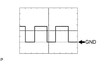 |
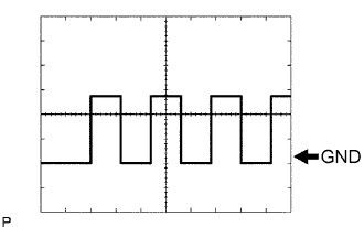
Waveform 1
|
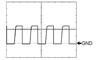
Waveform 2
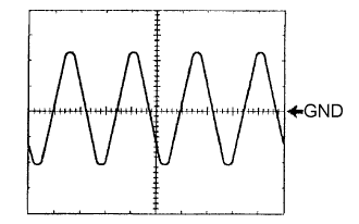 |
Waveform 3
 |
Waveform 4
 |
Waveform 5
|
Waveform 6
|
Waveform 7
