ELECTRONICALLY CONTROLLED BRAKE SYSTEM > SYSTEM DESCRIPTION |
| VDIM (Vehicle Dynamics Integrated Management) DESCRIPTION |
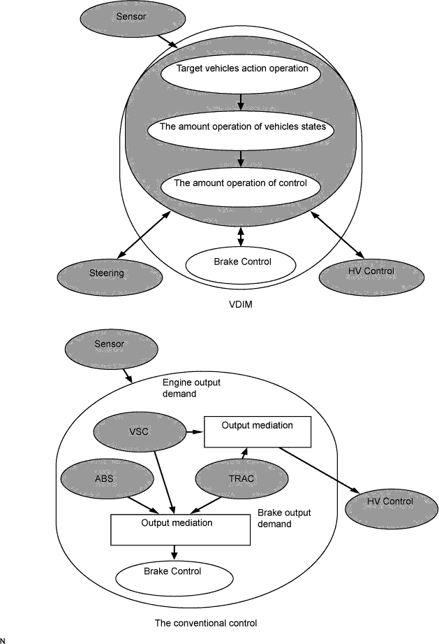
This vehicle is equipped with VDIM (Vehicle Dynamics Integrated Management). It is a concept of vehicle motion control that integrates brake control, drive force control and steering control.
Conventional vehicles use a combination of independent functions such as ABS, TRAC, VSC and EPS. However, VDIM integrates these systems to improve "drive, turn and stop," the motion performance of the vehicle in other words.
In conventional vehicles, control starts at the limit of the vehicle. However, VDIM exercises control before the limit is reached, creating a smooth vehicle response. This expands the limits of the vehicle, and increases driving pleasure.
The VDIM manages all functions, such as the ABS with EBD, the brake assist, the TRAC, and the VSC. It is operated by the ECB system, which regulates a brake fluid pressure. The steering cooperative control function is also available. Thus, the VDIM is able to perform the comprehensive management.
Conventional brake control systems begin to control either the braking or motive force in order to stabilize the vehicle motion when it becomes unstable due to loss of tire traction. In contrast, in order to maintain stable vehicle control, the VDIM commences controlling the brake and steering systems in accordance with changes in balance before the vehicle becomes unstable. As a result, smooth vehicle control is achieved.
Conventional brake control systems manage all related functions, such as the ABS with EBD, the brake assist, the TRAC and the VSC independently, according to the vehicle dynamics. In contrast, the VDIM provides smooth control by seamlessly integrating all those functions.
| ECB2 (Electronically Controlled Brake 2) SYSTEM DESCRIPTION |
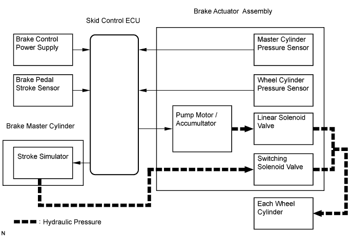
The system detects the degree of brake pedal operation with a brake pedal stroke sensor and two master cylinder pressure sensors, and calculates the optimum hydraulic brake force. The hydraulic pressure source is adjusted based on this so that the optimum hydraulic control is independently performed on all four wheels.
Meanwhile, the ECB2 system performs control of the normal brakes, ABS, TRAC, VSC and brake assist in accordance with the operations of the driver.
There is a hydraulic backup mechanism that applies master cylinder pressure generated by human power to the wheel cylinder when the brake control stops. In addition, as a fail safe mechanism, when the brake control is malfunctioning, the system excludes the malfunctioning sections and continues to perform brake control on the normal sections. A power backup unit (brake control power supply) is also used to ensure a stable supply of power to the system.
| FUNCTION DESCRIPTION |
ABS (Anti-lock Brake System)
The ABS helps prevent the wheels from locking when the brakes are applied suddenly and firmly or applied on a slippery surface.
Operation description
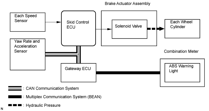
The skid control ECU detects wheel lock condition by receiving vehicle speed signals from each speed sensor, and sends control signals to the solenoid valve. The solenoid valve avoids wheel lock by controlling the oil pressure of each wheel cylinder.
The ABS warning light comes on when the ABS system is malfunctioning.
EBD (Electronic Brake force Distribution)
The EBD control utilizes ABS, performing proper brake force distribution between the front and rear wheels in accordance with driving conditions.
When braking while cornering, it also controls the brake forces of the right and left wheels, helping to maintain vehicle behavior.
Operation description
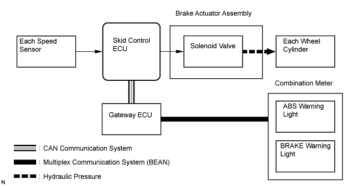
The skid control ECU receives the speed signal from each speed sensor to detect the slip condition of the wheels and sends the control signal to the solenoid.
The solenoid valve controls the oil pressure of each wheel cylinder and splits the control power properly between the front and rear wheels and the right and left wheels.
Both of the ABS and BRAKE warning lights come on to indicate a malfunction in the EBD system.
BA (Brake Assist)
The primary purpose of the brake assist system is to provide auxiliary brake force to assist the driver who cannot generate a brake force large enough during emergency braking, thus helping to maximize the vehicle's brake performance.
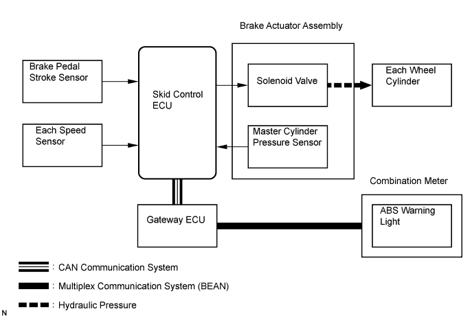
Operation description
The skid control ECU receives the brake pedal stroke sensor signal and the oil pressure signal from the master cylinder pressure sensor to determine whether brake assist is necessary or not. If brake assist is deemed necessary, the skid control ECU will send control signals to the solenoid. The solenoid valve then controls the pressure applied to each wheel cylinder.
The ABS warning light comes on to indicate a malfunction in the BA system.
TRAC (Traction Control)
The TRAC system helps prevent the drives wheels from slipping when the drive presses down on the accelerator pedal excessively while starting off or accelerating on a slippery surface.
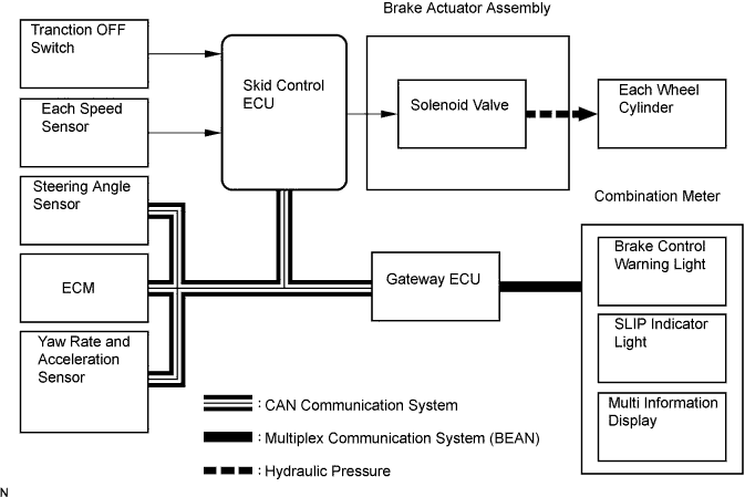
Operation description
The skid control ECU detects vehicle's slip condition by receiving signals from each speed sensor and ECM via CAN communication. The skid control ECU controls engine torque with the ECM via CAN communication and oil pressure through the pump and solenoid valve.
The SLIP indicator light blinks when the system is operating. When there is a malfunction in the TRAC system, both brake control warning light and SLIP indicator light come on and DTC will appear on the multi information display.
Traction OFF switch stops traction control operation.
VSC (Vehicle Stability Control)
The VSC system helps prevent the vehicle from slipping sideways as a result of strong front or rear wheel skid during cornering.
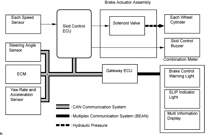
Operation description
The skid control ECU determines vehicle condition by receiving signals from the speed sensor, yaw rate and acceleration sensor and steering angle sensor. The skid control ECU controls engine torque with the ECM via CAN communication, and brake fluid pressure with the solenoid valve.
The SLIP indicator light blinks and the skid control buzzer sounds when the system is operating. When there is a malfunction in the VSC system, both brake control warning light and SLIP indicator light come on and DTC will appear on the multi information display.
| STEERING COOPERATION CONTROL |
The VDIM system effects coordinated control consisting of VSC and EPS (Electric Power Steering). By integrating these preventive safety functions, the VDIM system ensures higher driving stability and maneuverability performance.
If the vehicle loses stability due to a slippage, this function effects brake control by applying hydraulic pressure to the wheels. At the same time, the EPS provides steering torque assist to facilitate the driver's steering maneuver.
| PRE-COLLISION SAFETY CONTROL |
The pre-collision safety system predicts frontal collisions with other vehicles or obstructions. By winding up the seat belts prior to collision, and performing brake control and brake assist control, it lessens the impact during the collision.
The extremely high frequency radar recognizes if there is a vehicle or obstruction on the road ahead, and the distance control ECU makes a judgment from the position of the object, the speed and the road surface whether a collision is unavoidable.
The distance control ECU sends this information via a CAN communication to the seat belt control ECU, suspension control ECU and skid control ECU, to operate each control element of the pre-collision safety system.
| FUNCTION OF COMPONENTS |
| Components | Functions |
| Skid control ECU | Processes the signals from each sensor to perform brake control for ABS, TRAC, and VSC. In addition, it communicates with the ECM to output a control signal. |
| ABS MAIN relay (ABS No.1 relay, ABS No.2 relay) | Controlled by the skid control ECU. In addition to supplying power to each solenoid, it supplies power to the skid control ECU. |
| ABS MOTOR relay (ABS MTR1 relay, ABS MTR2 relay) | Controlled by the skid control ECU. Supplies power to the pump motor. |
| Speed sensor | Detects the wheel speed and inputs the results to the skid control ECU. |
| Stop light switch | Detects the brake operating conditions and inputs the results to the skid control ECU. It supplies power to the skid control ECU. |
| Brake pedal stroke sensor | Detects the brake pedal stroke volume and inputs the results to the skid control ECU. |
| Brake control power supply | Provides the system with a supplementary power supply by discharging the electric charge of the capacitor. It happens when an electric charge is accumulated in the capacitor in the unit and the vehicle power voltage (12 V) is reduced. |
| Skid control buzzer |
|
| HV control ECU | Controls the engine output during the operation of TRAC and VSC by communicating with the skid control ECU. |
| Yaw rate and deceleration sensor | Detects the yaw rate (axial rotation) and the forward, rearward and lateral acceleration, and inputs the results to the skid control ECU. |
| Steering angle sensor | Detects the steering angle and direction, and outputs the results to the skid control ECU via CAN communication. |
| Master cylinder | Generates pressure in accordance with the force of the brake operation. |
| Brake fluid reservoir | Stores brake fluid for the master cylinder system and power supply system. |
| Brake fluid level warning switch | Detects a reduction in the level of the brake fluid in the reservoir. |
| Stroke simulator | Generates a natural pedal stroke in accordance with the pedal force of the driver during system operation (integrated with the master cylinder). |
| Stroke simulator cut valve (SCSS) | Sends brake fluid pressure generated in master cylinder to stroke simulator during system control. |
| Brake actuator | Controls the hydraulic pressure of each of the four wheel cylinders using the output signal of the skid control ECU. |
| Pump motor | Pumps up the brake fluid from the reservoir and supplies the accumulator with high hydraulic pressure. |
| Accumulator | Stores hydraulic pressure that is generated by the pump. |
| Accumulator pressure sensor (PACC) | Built into the brake actuator to detect the accumulator hydraulic pressure. |
| Relief valve | Prevents excessive high pressure in the power supply system. It relieves the system by sending brake fluid to the reservoir when the pump has operated continuously, for example, during an accumulator hydraulic pressure sensor malfunction. |
| Master cylinder pressure sensor (PMC1, PMC2) | Built into the brake actuator to detect the pressure of the master cylinder and input the results to the skid control ECU. |
| Wheel cylinder pressure sensor (PFR, PFL, PRR, PRL) | Built into the brake actuator to detect the brake hydraulic pressure of each wheel cylinder. |
| Switching solenoid valve (SMC1, SMC2) | Switches the brake hydraulic pressure route according to whether normal brakes are used, or VDIM (ABS, TRAC and VSC) control are used. |
| Linear solenoid valve (SLA##, SLR##) | Controls the wheel cylinder hydraulic pressure during normal brake operation, and VDIM (ABS, TRAC and VSC) control. SLA## are solenoids for controlling pressure increases, while SLR## are solenoids for controlling pressure decreases. |
| ABS warning light |
|
| BRAKE warning light | Comes on to inform the driver that the parking brake is on when the system is normal or the brake fluid has decreased. |
| Brake control warning light | Comes on to inform the driver that a malfunction in the ECB system has occurred. |
| SLIP indicator light |
|
| Multi information display |
|
| FAIL SAFE |
When a failure occurs in the ABS with BA & TRAC & VSC systems, the ABS warning light and the brake control warning light come on and ABS with BA & TRAC & VSC operations will be prohibited. In addition to this, when there is a failure that disables the EBD operation, the BRAKE warning light also comes on and the EBD operation is prohibited.
If control is prohibited due to a malfunction during operation, control will be disabled gradually. This is to avoid sudden vehicle instability.
| SERVICE MODE |
VSC operation can be disables by operating the intelligent tester.
