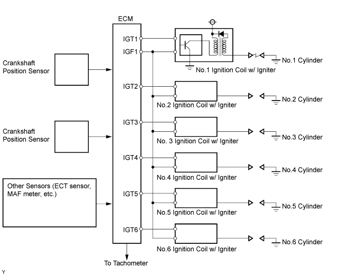
DTC P0351 Ignition Coil "A" Primary / Secondary Circuit |
DTC P0352 Ignition Coil "B" Primary / Secondary Circuit |
DTC P0353 Ignition Coil "C" Primary / Secondary Circuit |
DTC P0354 Ignition Coil "D" Primary / Secondary Circuit |
DTC P0355 Ignition Coil "E" Primary / Secondary Circuit |
DTC P0356 Ignition Coil "F" Primary / Secondary Circuit |
| DTC No. | DTC Detection Condition | Trouble Area |
| P0351 P0352 P0353 P0354 P0355 P0356 | No IGF signal to ECM while engine running (1 trip detection logic) |
|
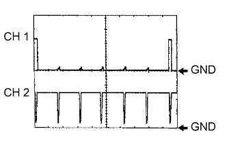
| Item | Content |
| Terminals | CH1: IGT1, IGT2, IGT3, IGT4, IGT5, IGT6 - E1 CH2: IGF1 - E1 |
| Equipment Settings | 2 V/Division, 20 ms/DIvision |
| Conditions | Cranking or idling |
| 1.PERFORM SIMULATION TEST |
Clear the DTC(s) (Click here).
Change the arrangement of the ignition coils (with igniters).
Reform a simulation test.
| Display (DTC Output) | Proceed to |
| Same DTCs (that have been erased) | A |
| Other DTCs | B |
|
| ||||
| A | |
| 2.INSPECT IGNITION COIL ASSEMBLY (POWER SOURCE) |
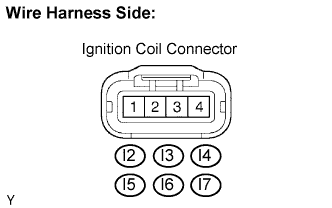 |
Disconnect the I2, I3, I4, I5, I6 or I7 ignition coil connector.
Turn the ignition switch ON.
Measure the voltage between the terminal of the wire harness side connector and body ground.
| Tester Connection | Specified Condition |
| I2-1 - Body ground | 9 to 14 V |
| I3-1 - Body ground | 9 to 14 V |
| I4-1 - Body ground | 9 to 14 V |
| I5-1 - Body ground | 9 to 14 V |
| I6-1 - Body ground | 9 to 14 V |
| I7-1 - Body ground | 9 to 14 V |
Measure the resistance between the wire harness side connectors.
| Tester Connection | Specified Condition |
| I2-4 - Body ground | Below 1 Ω |
| I3-4 - Body ground | Below 1 Ω |
| I4-4 - Body ground | Below 1 Ω |
| I5-4 - Body ground | Below 1 Ω |
| I6-4 - Body ground | Below 1 Ω |
| I7-4 - Body ground | Below 1 Ω |
|
| ||||
| OK | |
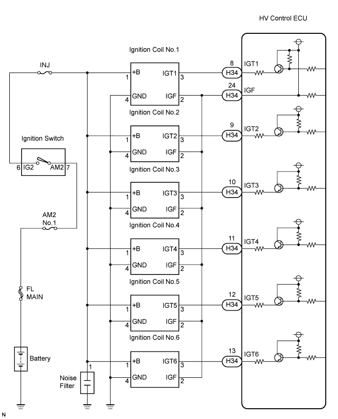
| 3.CHECK HARNESS AND CONNECTOR (IGNITION COIL ASSEMBLY - HV CONTROL ECU) |
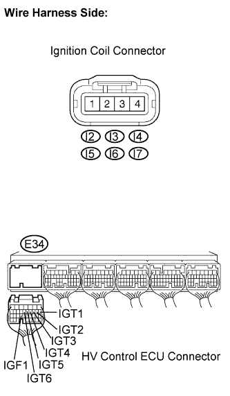 |
Disconnect the I2, I3, I4, I5, I6 or I7 ignition coil connector.
Disconnect the HV Control ECU H34 connectors.
Measure the resistance between the wire harness side connectors.
| Tester Connection | Specified Condition |
| IGT1 (I2-3) - IGT1 (H34-8) | Below 1 Ω |
| IGT2 (I3-3) - IGT2 (H34-9) | Below 1 Ω |
| IGT3 (I4-3) - IGT3 (H34-10) | Below 1 Ω |
| IGT4 (I5-3) - IGT4 (H34-11) | Below 1 Ω |
| IGT5 (I6-3) - IGT5 (H34-12) | Below 1 Ω |
| IGT6 (I7-3) - IGT6 (H34-13) | Below 1 Ω |
| Tester Connection | Specified Condition |
| IGT1 (I2-3) - IGT1 (H34-8) - Body ground | 10 kΩ or higher |
| IGT2 (I3-3) - IGT2 (H34-9) - Body ground | 10 kΩ or higher |
| IGT3 (I4-3) - IGT3 (H34-10) - Body ground | 10 kΩ or higher |
| IGT4 (I5-3) - IGT4 (H34-11) - Body ground | 10 kΩ or higher |
| IGT5 (I6-3) - IGT5 (H34-12) - Body ground | 10 kΩ or higher |
| IGT6 (I7-3) - IGT6 (H34-13) - Body ground | 10 kΩ or higher |
| Tester Connection | Specified Condition |
| IGF1 (I2-2) - IGF1 (H34-24) | Below 1 Ω |
| IGF2 (I3-2) - IGF1 (H34-24) | Below 1 Ω |
| IGF3 (I4-2) - IGF1 (H34-24) | Below 1 Ω |
| IGF4 (I5-2) - IGF1 (H34-24) | Below 1 Ω |
| IGF5 (I6-2) - IGF1 (H34-24) | Below 1 Ω |
| IGF6 (I7-2) - IGF1 (H34-24) | Below 1 Ω |
| Tester Connection | Specified Condition |
| IGF1 (I2-2) or IGF1 (H34-24) - Body ground | 10 kΩ or higher |
| IGF2 (I3-2) or IGF1 (H34-24) - Body ground | 10 kΩ or higher |
| IGF3 (I4-2) or IGF1 (H34-24)- Body ground | 10 kΩ or higher |
| IGF4 (I5-2) or IGF1 (H34-24) - Body ground | 10 kΩ or higher |
| IGF5 (I6-2) or IGF1 (H34-24) - Body ground | 10 kΩ or higher |
| IGF6 (I7-2) or IGF1 (H34-24)- Body ground | 10 kΩ or higher |
|
| ||||
| OK | |
| 4.CHECK ECM (IGT1, IGT2, IGT3, IGT4, IGT5, IGT6, IGF1 SIGNAL) |
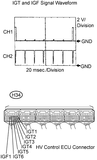 |
Inspect using an oscilloscope.
Put the engine in inspection mode (Click here).
Start the engine.
Check the waveform of the HV Control ECU connectors.
| Tester Connection | Specified Condition |
| IGF1 (H34-24) - E1 (H31-5) | Correct waveform is shown |
| IGT1 (H34-8) - E1 (H31-5) | |
| IGT2 (H34-9) - E1 (H31-5) | |
| IGT3 (H34-10) - E1 (H31-5) | |
| IGT4 (H34-11) - E1 (H31-5) | |
| IGT5 (H34-12) - E1 (H31-5) | |
| IGT6 (H34-13) - E1 (H31-5) |
|
| ||||
| OK | |
| 5.CHECK IF DTC OUTPUT RECURS |
Clear the DTC (Click here).
Connect the intelligent tester to the DLC3.
Turn the ignition switch ON and turn the intelligent tester ON.
Enter the following menus: Powertrain / Engine / DTC.
Read DTC.
| Display (DTC Output) | Proceed to |
| P0351, P0352, P0353, P0354, P0355 and/or P0356 are output | A |
| No output | B |
|
| ||||
| A | ||
| ||
