CAN COMMUNICATION SYSTEM (for RHD) > Open in One Side of CAN Sub Bus Line |
| Symptom | Suspected Area |
| 2 or more ECUs and/or sensors do not appear on the intelligent tester "Communication Bus Check" screen. |
|
| 1.CHECK FOR AN OPEN IN ONE SIDE OF THE CAN SUB BUS LINE |
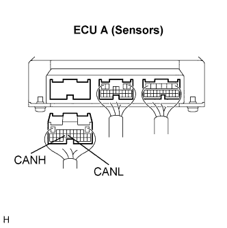 |
Disconnect the connector with terminals CANH and CANL of the ECU A (SENSORS).
Select "Check the ECU connected to CAN BUS "on the intelligent tester.
| Result | Proceed to |
| ECUs only are not displayed on the intelligent tester. | A |
| B |
|
| ||||
| A | |
| 2.CHECK FOR AN OPEN IN ONE SIDE OF THE CAN SUB BUS LINE |
|
Measure the resistance according to the value(s) in the table below.
| ECU (Sensor) | Condition | Specified Value |
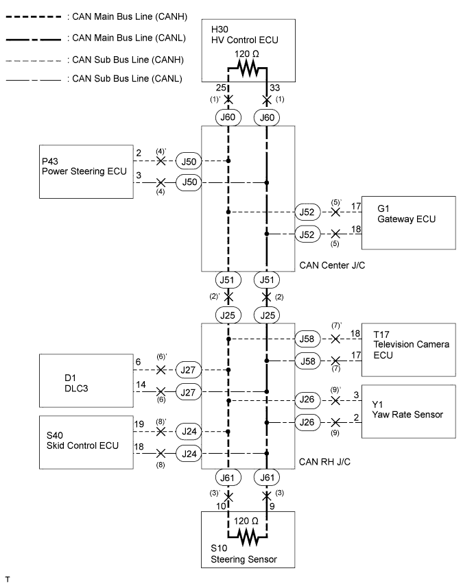
| HV control ECU | Disconnect the negative auxiliary battery cable | 108 to 132 Ω |
| Steering sensor | Disconnect the negative auxiliary battery cable | 108 to 132 Ω |
| Others | Disconnect the negative auxiliary battery cable | 54 to 69 Ω |
|
| ||||
| OK | ||
| ||
