DTC P2238 Oxygen (A/F) Sensor Pumping Current Circuit Low (Bank 1 Sensor 1) |
DTC P2239 Oxygen (A/F) Sensor Pumping Current Circuit High (Bank 1 Sensor 1) |
DTC P2241 Oxygen (A/F) Sensor Pumping Current Circuit Low (Bank 2 Sensor 1) |
DTC P2242 Oxygen (A/F) Sensor Pumping Current Circuit High (Bank 2 Sensor 1) |
DTC P2252 Oxygen (A/F) Sensor Reference Ground Circuit Low (Bank 1 Sensor 1) |
DTC P2253 Oxygen (A/F) Sensor Reference Ground Circuit High (Bank 1 Sensor 1) |
DTC P2255 Oxygen (A/F) Sensor Reference Ground Circuit Low (Bank 2 Sensor 1) |
DTC P2256 Oxygen (A/F) Sensor Reference Ground Circuit High (Bank 2 Sensor 1) |
| DTC No. | DTC Detection Condition | Trouble Area |
| P2238 P2241 |
|
|
| P2239 P2242 | AF+ voltage more than 4.5 V for 5.0 seconds or more (2 trip detection logic) |
|
| P2252 P2255 | AF- voltage 0.5 V or less for 5.0 seconds or more (2 trip detection logic) |
|
| P2253 P2256 | AF- voltage more than 4.5 V for 5.0 seconds or more (2 trip detection logic) |
|
| Tester Display (Sensor) | Injection Volume | Status | Voltage |
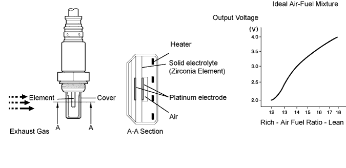
| AFS B1S1 or AFS B2S1 (A/F) | +25 % | Rich | Less than 3.0 |
| AFS B1S1 or AFS B2S1 (A/F) | -12.5 % | Lean | More than 3.35 |
| O2S B1S2 or O2S B2S2 (HO2) | +25 % | Rich | More than 0.55 |
| O2S B1S2 or O2S B2S2 (HO2) | -12.5 % | Lean | Less than 0.4 |
| Case | A/F Sensor (Sensor 1) Output Voltage | HO2 Sensor (Sensor 2) Output Voltage | Main Suspected Trouble Areas | ||
| 1 | Injection Volume +25 % -12.5 % |  | Injection Volume +25 % -12.5 % | | - |
| Output Voltage More than 3.35 V Less than 3.0 V |  | Output Voltage More than 0.55 V Less than 0.4 V |  | ||
| 2 | Injection Volume +25 % -12.5 % | | Injection Volume +25 % -12.5 % | |
|
| Output Voltage Almost no reaction |  | Output Voltage More than 0.55 V Less than 0.4 V | | ||
| 3 | Injection Volume +25 % -12.5 % | | Injection Volume +25 % -12.5 % | |
|
| Output Voltage More than 3.35 V Less than 3.0 V | | Output Voltage Almost no reaction | | ||
| 4 | Injection volume +25 % -12.5 % | | Injection Volume +25 % -12.5 % | |
|
| Output Voltage Almost no reaction | | Output Voltage Almost no reaction | | ||
| 1.INSPECT AIR FUEL RATIO SENSOR (HEATER RESISTANCE) |
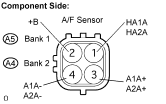 |
Disconnect the A4 or A5 Air-Fuel Ratio (A/F) sensor connector.
Measure the resistance between the terminals of the A/F sensor connector.
| Tester Connection | Specified Condition |
| HA1A, HA2A (1) - +B (2) | 1.8 to 3.4 Ω at 20°C (68°F) |
| HA1A, HA2A (1) - A1A-, A2A- (4) | 10 kΩ or higher |
Reconnect the A/F sensor connector.
|
| ||||
| OK | |
| 2.INSPECT A/F RELAY |
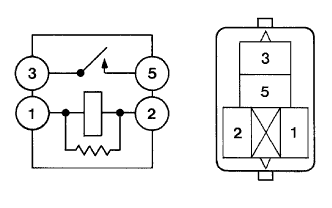 |
Remove the A/F relay from the engine room R/B.
Measure the A/F relay resistance.
| Tester Connection | Specified Condition |
| 3 - 5 | 10 kΩ or higher |
| 3 - 5 | Below 1 Ω (when battery voltage applied to terminals 1 and 2) |
Reinstall the A/F HTR relay.
|
| ||||
| OK | |
| 3.CHECK HARNESS AND CONNECTOR (A/F SENSOR - HV CONTROL ECU) |
 |
Disconnect the A4 and A5 A/F sensor connector.
Turn the ignition switch ON.
Measure the voltage between the +B terminal of the A/F sensor connector and body ground.
| Tester Connection | Specified Condition |
| +B (A4-2) - Body ground | 9 to 14 V |
| +B (A5-2) - Body ground | 9 to 14 V |
Turn the engine switch off.
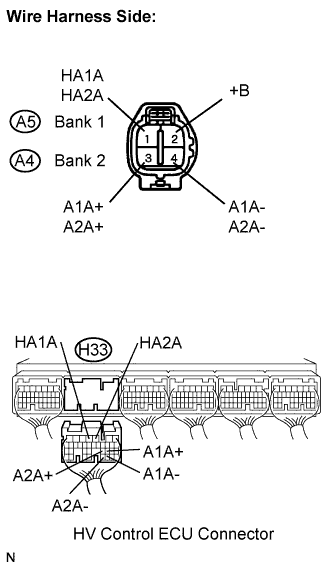
Disconnect the H33 HV Control ECU connector.
Check the resistance.
| Tester Connection | Specified Condition |
| HA1A ( A5-1) - HA1A (H33-4) | Below 1 Ω |
| A1A+ (A5-3) - A1A+ (H33-22) | Below 1 Ω |
| A1A- (A5-4) - A1A- (H33-30) | Below 1 Ω |
| HA2A (A4-1) - HA2A (H33-3) | Below 1 Ω |
| A2A+ (A4-3) - A2A+ (H33-23) | Below 1 Ω |
| A2A- (A4-4) - A2A- (H33-31) | Below 1 Ω |
| Tester Connection | Specified Condition |
| HA1A ( A5-1) or HA1A (H33-4) - Body ground | 10 kΩ or higher |
| A1A+ (A5-3) or A1A+ (H33-22) - Body ground | 10 kΩ or higher |
| A1A- (A5-4) or A1A- (H33-30) - Body ground | 10 kΩ or higher |
| HA2A (A4-1) or HA2A (H33-3) - Body ground | 10 kΩ or higher |
| A2A+ (A4-3) or A2A+ (H33-23) - Body ground | 10 kΩ or higher |
| A2A- (A4-4) or A2A- (H33-31) - Body ground | 10 kΩ or higher |
Reconnect the HV Control ECU connector.
Reconnect the A/F sensor connector.
|
| ||||
| OK | ||
| ||
