ELECTRONIC POWER STEERING SYSTEM > PRECAUTION |
| 1.PRECAUTIONS FOR INSPECTING HIGH-VOLTAGE SYSTEM |
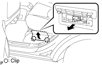 |
Before inspecting the high-voltage system, take safety precautions to prevent electrical shocks, such as wearing insulated gloves and removing the service plug grip. After removing the service plug grip, put it in your pocket to prevent other technicians from reconnecting it while you are working on the high-voltage system.
After disconnecting the service plug grip, wait for at least 5 minutes before touching any of the high-voltage connectors or terminals.
Wear protective goggles to prevent eye injury from electrolyte leakage when checking inside the HV battery.
Wear insulated gloves, turn the ignition switch off, and disconnect the negative terminal of the auxiliary battery before touching any of the orange-colored wires of the high-voltage system.
Turn the ignition switch off before performing a resistance check.
Turn the ignition switch off before disconnecting or reconnecting any connector.
To install the service plug grip, the lever must be flipped down. If the lever is not flipped down, interlock switch system DTCs will be output.
| 2.NOTICE FOR INITIALIZATION |
| System Name | See procedure |
| Lighting System |
Click here
|
| Sliding Roof Control System | |
| Power Window Control System | |
| Power Door Lock Control System | |
| Power Back Door System | |
| Back Door Closer System | |
| Electrical Back Door Outside Handle System | |
| SFI System |
| 3.HANDLING PRECAUTIONS |
When handling the electronic parts:
Avoid any impact to electronic parts such as ECUs and relays. Replace these parts with new ones if dropped or subjected to a severe blow.
Do not expose any electronic parts to high temperature or humidity.
Do not touch the connector terminals in order to prevent deformation or malfunctions due to static electricity.
If the power steering ECU assembly has been replaced with a new one, initialize the rotation angle sensor value and calibrate the torque sensor zero point (Click here).
When handling the power steering link assembly:
Avoid any impact to the power steering link assembly, especially to the motor or torque sensor. Replace with new parts if dropped or subjected to a severe blow.
Do not pull on the wire harness when moving the power steering link assembly.
If the power steering link assembly has been replaced with a new one, clear the rotation angle sensor calibration value, initialize the rotation angle sensor value, and calibrate the torque sensor zero point (Click here).
When disconnecting and reconnecting the connectors:
Turn the ignition switch to the ON position, center the steering wheel, and turn the ignition switch off again before disconnecting the connectors related to the electronic power steering system.
Ensure that the ignition switch is off before reconnecting the connectors related to the electronic power steering system. After reconnection, center the steering wheel and turn the ignition switch to the ON position.
If the above operations are not carried out properly, the steering center point (zero point) will deviate, which may lead to a difference in steering effort between right and left. If there is a difference in steering effort between right and left, perform steering zero point calibration (Click here).
| 4.PRECAUTIONS FOR CAN COMMUNICATION |
CAN communication is used to receive information from the skid control ECU, steering control ECU, ECM and steering angle sensor and to transmit warnings to the combination meter. It is also used for communication between terminals Tc and Ts of the DLC3. If there are any problems in the CAN communication lines, DTCs indicating communication line malfunctions are output.
Perform troubleshooting for communication line problems if CAN communication DTCs are output. Be sure to start troubleshooting on the electric power steering system only when data communication is normal.
Temporary fixing or repair with bypass wiring, etc. is impossible because the length and path of each CAN communication line is specified.
| 5.BUS LINE REPAIR |
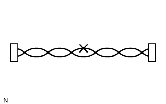 |
After repairing the bus line with solder, wrap the repaired part with vinyl tape.
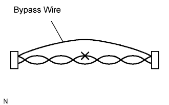 |
Do not use bypass wiring between the connectors.
