ELECTRONIC POWER STEERING SYSTEM > SYSTEM DESCRIPTION |
| DESCRIPTION |
The EPS system generates torque through the operation of the motor installed on the power steering link assembly in order to assist steering effort.
Directions and amount of assisting power are determined by signals from the torque sensor, and controlled in accordance with vehicle speed. As a result, steering effort is controlled to be light during low speed driving and moderately high during high speed driving.
| FUNCTIONS OF COMPONENTS |
| Components | Function |
| Power Steering ECU Assembly | Calculates degree of assistance needed based on steering torque and vehicle speed. Drives the motor based on motor electric angle obtained from the motor rotation angle sensor. |
| Boosts battery voltage to generate motor drive voltage. | |
| Restricts power assistance to protect the system if the motor and ECU overheat. | |
| In accordance with signals received from various sensors and the skid control ECU, the power steering ECU operates the motor in the power steering link assembly for the purpose of providing power assist. | |
| Torque Sensors | Detect steering effort generated when the steering wheel is turned. |
| Power Steering Motor | Located coaxially with the rack shaft. Its rotation is converted to the rectilinear motion of the steering rack via the ball screw nut and ball. |
| Motor Rotation Angle Sensor | Detects motor rotation angle. |
| Power Steering Converter | Activated and stopped by the power steering ECU assembly. Reduces the voltage supplied from the high-voltage battery and outputs a voltage of 42 V as a power source for the power steering motor. |
| HV Control ECU | Transmits a READY signal to the power steering ECU assembly, in order to inform the electronic power steering system that it is ready to generate electricity. |
| Skid Control ECU | Outputs vehicle speed signals to the power steering ECU assembly. Transmits an additional torque signal (which is calculated in accordance with the signals from the sensors for the purpose of effecting cooperative control) to the power steering ECU assembly while the VSC (Vehicle Stability Control) function is operating. |
| Combination Meter | Turn on the P/S warning light upon receiving a signal from the power steering ECU assembly in the event of a system malfunction. |
| OPERATION EXPLANATION |
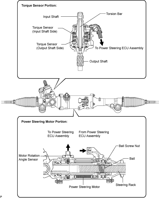
The torque sensors are mounted on the input shaft to the main shaft and on the output shaft to the pinion shaft. The input and output shafts are joined by a torsion bar.
If the steering wheel is turned, the torsion bar twists, resulting in a difference in the rotation angle detected by each torque sensor. The power steering ECU assembly calculates torque based on this difference.
The power steering ECU assembly calculates proper assisting torque, according to vehicle speed, based on the torque obtained in the previous step. Then the ECU controls the motor drive circuit in order to cause it to generate assisting torque.
A ball screw nut is attached to the motor shaft. It converts the rotational motion of the motor into the rectilinear motion of the steering rack via the ball.
The assisting force generated in the above process will reduce the steering effort required by the driver.
