ELECTRONIC POWER STEERING SYSTEM > DIAGNOSIS SYSTEM |
| DESCRIPTION |
Connecting the intelligent tester to the vehicle and reading various data output from the power steering ECU assembly is the only difference between usual troubleshooting procedures and those for a vehicle with a diagnostic system.
The power steering ECU assembly records DTCs when the ECU detects a malfunction in the computer itself or in its circuits.
To check the DTCs, connect the intelligent tester to the DLC3. The intelligent tester enables you to erase the DTCs and check the freeze frame data and various forms of steering data.
| CHECK DLC3 |
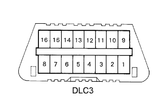 |
Check the DLC3.
The power steering ECU assembly uses CAN and ISO 9141-2 (Euro-OBD)/ISO 14230 (M-OBD) for communication protocol. The terminal arrangement of the DLC3 complies with ISO 15031-03 and matches the ISO 9141-2/ISO 14230 format.
| Symbols (Terminal No.) | Terminal Description | Condition | Specified Condition |
| SIL (7) - SG (5) | Bus "+" line | During communication | Pulse generation |
| CG (4) - Body ground | Chassis ground | Always | Below 1 Ω |
| SG (5) - Body ground | Signal ground | Always | Below 1 Ω |
| BAT (16) - Body ground | Battery positive | Always | 11 to 14 V |
| CANH (6) - CANL (14) | HIGH-level CAN bus line | Ignition switch off | 54 to 67 Ω |
| CANH (6) - Battery positive | HIGH-level CAN bus line | Ignition switch off | 1 MΩ or higher |
| CANH (6) - CG (4) | HIGH-level CAN bus line | Ignition switch off | 3 kΩ or higher |
| CANL (14) - Battery positive | LOW-level CAN bus line | Ignition switch off | 1 MΩ or higher |
| CANL (14) - CG (4) | LOW-level CAN bus line | Ignition switch off | 3 kΩ or higher |
| P/S WARNING LIGHT |
If a problem occurs in the electronic power steering system, the P/S warning light will come on in the combination meter.
