DTC B2610 Tilt Position Sensor or Tilt Motor Circuit Malfunction |
| DTC No. | Detection Item | Trouble Area |
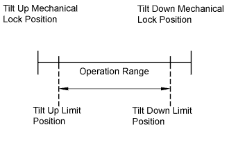
| B2610 | Tilt operation stops within the operation range while operating. |
|
| 1.PERFORM ACTIVE TEST BY INTELLIGENT TESTER |
 |
Connect the intelligent tester to the DLC3.
Turn the ignition switch to the ON position and turn the intelligent tester on.
Select "Tilt & Telescopic".
Touch the "Active Test" button.
Select "Tilt Operation", and perform the test using the intelligent tester.
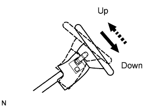
Check that the steering wheel tilts up (down) when the Active Test is carried out.
|
| ||||
| NG | |
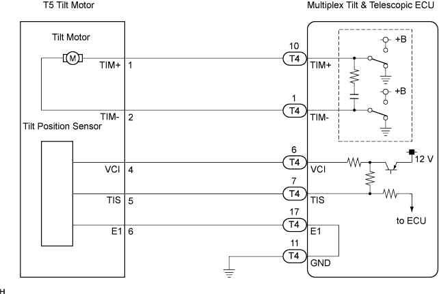
| 2.CHECK HARNESS AND CONNECTOR (BETWEEN TILT & TELESCOPIC ECU AND TILT MOTOR) |
 |
Disconnect the T4 connector from the multiplex tilt & telescopic ECU.
Disconnect the T5 connector from the tilt motor.
Measure the resistance according to the value(s) in the table below.
| Tester connection (Terminal No.) | Condition | Specified value |
| TIM+ (T4-10) - TIM+ (T5-1) | Always | Below 1 Ω |
| TIM- (T4-1) - TIM- (T5-2) | Always | Below 1 Ω |
| TIM+ (T4-10) - Body ground | Always | 10 kΩ or higher |
| TIM- (T4-1) - Body ground | Always | 10 kΩ or higher |
|
| ||||
| OK | |
| 3.INSPECT TILT MOTOR |
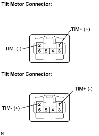 |
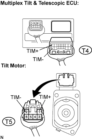
Connect the positive battery terminal to terminal TIM+ and the negative battery terminal to terminal TIM- of the tilt motor connector. Then confirm that the steering wheel tilts up.
Connect the negative battery terminal to terminal TIM+ and the positive battery terminal to terminal TIM- of the tilt motor connector. Then confirm that the steering wheel tilts down.
|
| ||||
| OK | ||
| ||
| 4.CHECK HARNESS AND CONNECTOR (BETWEEN TILT & TELESCOPIC ECU AND TILT POSITION SENSOR) |
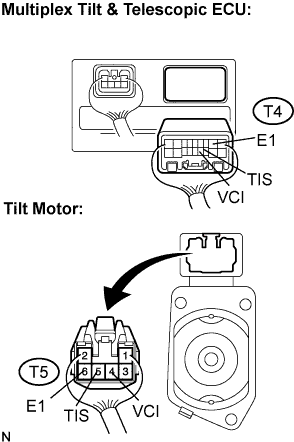 |
Disconnect the T4 connector from the multiplex tilt & telescopic ECU.
Disconnect the T5 connector from the tilt motor.
Measure the resistance according to the value(s) in the table below.
| Tester connection (Terminal No.) | Condition | Specified value |
| VCI (T4-6) - VCI (T5-4) | Always | Below 1 Ω |
| TIS (T4-7) - TIS (T5-5) | Always | Below 1 Ω |
| E1 (T4-17) - E1 (T5-6) | Always | Below 1 Ω |
| VCI (T4-6) - Body ground | Always | 10 kΩ or higher |
| TIS (T4-7) - Body ground | Always | 10 kΩ or higher |
| E1 (T4-17) - Body ground | Always | 10 kΩ or higher |
|
| ||||
| OK | |
| 5.CHECK HARNESS AND CONNECTOR (BETWEEN TILT & TELESCOPIC ECU AND BODY GROUND) |
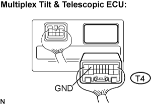 |
Measure the resistance according to the value(s) in the table below.
| Tester connection (Terminal No.) | Condition | Specified value |
| GND (T4-11) - Body ground | Always | Below 1 Ω |
|
| ||||
| OK | |
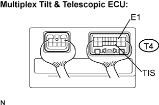
| 6.INSPECT MULTIPLEX TILT & TELESCOPIC ECU (VCI, TIS TERMINAL VOLTAGE) |
 |
Reconnect the T4 connector to the multiplex tilt & telescopic ECU.
Measure the voltage according to the value(s) in the table below.
| Tester connection (Terminal No.) | Condition | Specified value |
| VCI (T5-4) - E1 (T5-6) | Ignition switch on | 8 to 16 V |
| TIS (T5-5) - E1 (T5-6) | Ignition switch on | 8 to 16 V |
|
| ||||
| OK | |
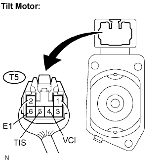
| 7.INSPECT TILT POSITION SENSOR |
 |
Reconnect the T5 connector to the tilt motor.
Measure the voltage according to the value(s) in the table below.
| Tester connection (Terminal No.) | Condition | Specified value |
| TIS (T4-7) - E1 (T4-17) | Steering tilts up or tilts down | 8 to 16 V (Pulse HI) |
| 0 V (Pulse LOW) |
|
| ||||
| OK | ||
| ||
