DTC B2611 Telescopic Position Sensor or Telescopic Motor Circuit Malfunction |
| DTC No. | Detection Item | Trouble Area |
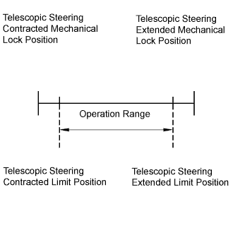
| B2611 | Telescopic operation stops within the operation range while operating. |
|
| 1.PERFORM ACTIVE TEST BY INTELLIGENT TESTER |
 |
Connect the intelligent tester to the DLC3.
Turn the ignition switch to the ON position and turn the intelligent tester on.
Select "Tilt & Telescopic".
Touch the "Active Test" button.
Select "Telesco Operation", and perform the test using the intelligent tester.
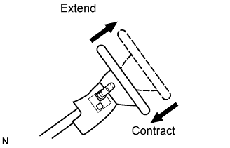
Check that the steering column contracts (extends) when the Active Test is carried out.
|
| ||||
| NG | |
| 2.INSPECT TELESCOPIC MOTOR |
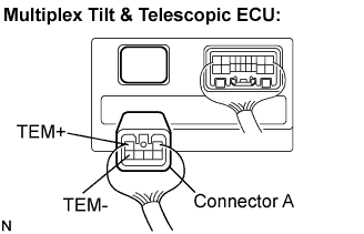 |
Disconnect connector A from the multiplex tilt & telescopic ECU.
Connect the positive battery terminal to terminal TEM+ and the negative battery terminal to terminal TEM- of the telescopic motor connector. Then confirm that the steering column contracts.
Connect the negative battery terminal to terminal TEM+ and the positive battery terminal to terminal TEM- of the telescopic motor connector. Then confirm that the steering column extends.
|
| ||||
| OK | ||
| ||
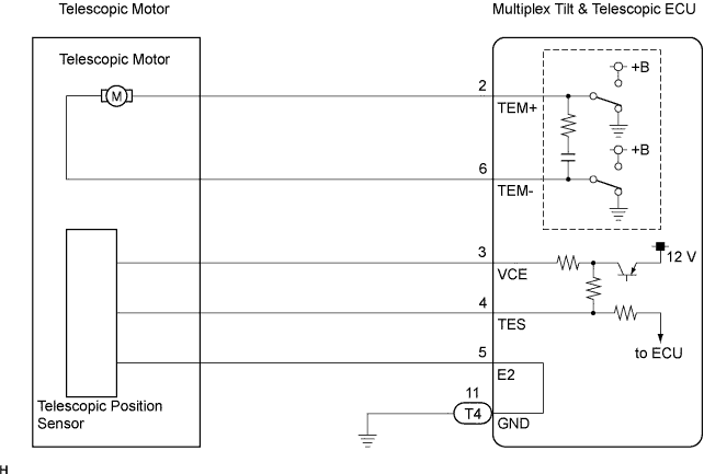
| 3.INSPECT MULTIPLEX TILT & TELESCOPIC ECU (VCE TERMINAL VOLTAGE) |
 |
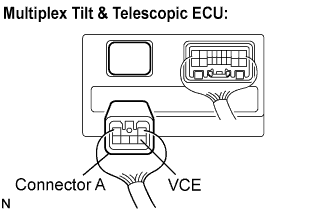
Measure the voltage according to the value(s) in the table below.
| Tester connection | Condition | Specified value |
| VCE - E2 | Ignition switch on | 8 to 16 V |
|
| ||||
| OK | |
| 4.INSPECT TELESCOPIC POSITION SENSOR |
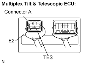 |
Measure the voltage according to the value(s) in the table below.
| Tester connection | Condition | Specified value |
| TES - E2 | Telescopic steering contracts or extends | 8 to 16 V (Pulse HI) |
| 0 V (Pulse LOW) |
|
| ||||
| OK | ||
| ||
| 5.CHECK HARNESS AND CONNECTOR (BETWEEN TILT & TELESCOPIC ECU AND TELESCOPIC POSITION SENSOR) |
 |
Disconnect connector A from the multiplex tilt & telescopic ECU.
Measure the resistance according to the value(s) in the table below.
| Tester connection | Condition | Specified value |
| VCE - Body ground | Always | 10 kΩ or higher |
|
| ||||
| OK | |
| 6.CHECK HARNESS AND CONNECTOR (BETWEEN TILT & TELESCOPIC ECU AND BODY GROUND) |
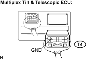 |
Disconnect the T4 connector from the multiplex tilt & telescopic ECU.
Measure the resistance according to the value(s) in the table below.
| Tester connection (Terminal No.) | Condition | Specified value |
| GND (T4-11) - Body ground | Always | Below 1 Ω |
|
| ||||
| OK | ||
| ||
