DTC P0343-747 Camshaft Position Sensor "A" Circuit High Input |
| DTC No. | INF Code | DTC Detection Condition | Trouble Area |
| P0343 | 747 | GI signal is not input for 1 sec. or more while the engine is running. |
|
| 1.READ OUTPUT DTC (SFI SYSTEM) |
Connect the intelligent tester to the DLC3.
Turn the ignition switch to the ON position.
Select the following menu items: Powertrain / Engine / DTC.
Read output DTC. (Click here)
|
| ||||
| NO | |
| 2.READ OUTPUT DTC (HV) |
Connect the intelligent tester to the DLC3.
Turn the ignition switch to the ON position.
Select the following menu items: Powertrain / Hybrid Control / DTC.
Read output DTC. (Click here)
| DTC No. | Relevant Diagnosis |
| P0A3F-243, P0A40-500, P0A4D-255, P0A1A-791, P0A1A-793, P0A1B-795, P0A41-245, P0A4B-253, P0A4C-513, P0A1A-792, P0A1B-794, P0A1B-796 | Motor resolver circuit, Generator resolver circuit |
|
| ||||
| NO | |
| 3.CHECK CONNECTION CONDITION OF HYBRID VEHICLE CONTROL ECU CONNECTOR (LOOSENESS AND POOR CONTACT) |
 |
Check the connections of all HV control ECU connectors.
|
| ||||
| OK | |
| 4.CHECK CONNECTION CONDITION OF MG ECU CONNECTOR (LOOSENESS AND POOR CONTACT) |
Turn the ignition switch off and remove the service plug grip. (Click here)
Remove the inverter cover. (Click here)
 |
Check the connections of the MG ECU connectors.
|
| ||||
| OK | |
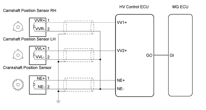
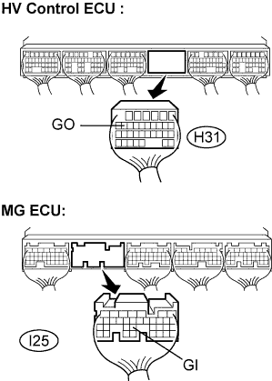
| 5.CHECK HARNESS AND CONNECTOR (HV CONTROL ECU - MG ECU) |
Disconnect the H31 HV control ECU connector.
Disconnect the I25 MG ECU connector.
 |
Measure the resistance according to the value(s) in the table below.
| Tester Connection | Specified Condition |
| GO (H31-15) - GI (I25-24) | Below 1 Ω |
| Tester Connection | Specified Condition |
| GO (H31-15) or GI (I25-24) - Body ground | 10 kΩ or more |
|
| ||||
| OK | |
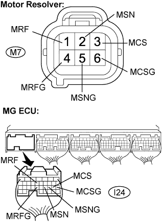
| 6.CHECK HARNESS AND CONNECTOR (MG ECU - MOTOR RESOLVER) |
Check that the service plug grip is removed.
Disconnect the M7 motor resolver connector.
Disconnect the I24 MG ECU connector.
 |
Measure the voltage according to the value(s) in the table below when the ignition switch is in the ON position.
| Tester Connection | Specified Condition |
| MRF (I24-13) - Body ground | Below 1 V |
| MRFG (I24-23) - Body ground | Below 1 V |
| MSN (I24-21) - Body ground | Below 1 V |
| MSNG (I24-20) - Body ground | Below 1 V |
| MCS (I24-19) - Body ground | Below 1 V |
| MCSG (I24-18) - Body ground | Below 1 V |
Turn the ignition switch off.
Measure the resistance according to the value(s) in the table below.
| Tester Connection | Specified Condition |
| MRF (I24-13) - MRF (M7-1) | Below 1 Ω |
| MRFG (I24-23) - MRFG (M7-4) | Below 1 Ω |
| MSN (I24-21) - MSN (M7-2) | Below 1 Ω |
| MSNG (I24-20) - MSNG (M7-5) | Below 1 Ω |
| MCS (I24-19) - MCS (M7-3) | Below 1 Ω |
| MCSG (I24-18) - MCSG (M7-6) | Below 1 Ω |
| Tester Connection | Specified Condition |
| MRF (I24-13) or MRF (M7-1) - Body ground | 10 kΩ or more |
| MRFG (I24-23) or MRFG (M7-4) - Body ground | 10 kΩ or more |
| MSN (I24-21) or MSN (M7-2) - Body ground | 10 kΩ or more |
| MSNG (I24-20) or MSNG (M7-5) - Body ground | 10 kΩ or more |
| MCS (I24-19) or MCS (M7-3) - Body ground | 10 kΩ or more |
| MCSG (I24-18) or MCSG (M7-6) - Body ground | 10 kΩ or more |
|
| ||||
| OK | |
| 7.CHECK HARNESS AND CONNECTOR (MG ECU - GENERATOR RESOLVER) |
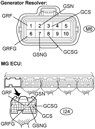 |
Disconnect the M6 generator resolver connector.
Measure the voltage according to the value(s) in the table below when the ignition switch is in the ON position.
| Tester Connection | Specified Condition |
| GRF (I24-12) - Body ground | Below 1 V |
| GRFG (I24-22) - Body ground | Below 1 V |
| GSN (I24-11) - Body ground | Below 1 V |
| GSNG (I24-10) - Body ground | Below 1 V |
| GCS (I24-9) - Body ground | Below 1 V |
| GCSG (I24-8) - Body ground | Below 1 V |
Turn the ignition switch off.
Measure the resistance according to the value(s) in the table below.
| Tester Connection | Specified Condition |
| GRF (I24-12) - GRF (M6-1) | Below 1 Ω |
| GRFG (I24-22) - GRFG (M6-6) | Below 1 Ω |
| GSN (I24-11) - GSN (M6-2) | Below 1 Ω |
| GSNG (I24-10) - GSNG (M6-7) | Below 1 Ω |
| GCS (I24-9) - GCS (M6-3) | Below 1 Ω |
| GCSG (I24-8) - GCSG (M6-8) | Below 1 Ω |
| Tester Connection | Specified Condition |
| GRF (I24-12) or GRF (M6-1) - Body ground | 10 kΩ or more |
| GRFG (I24-22) or GRFG (M6-6) - Body ground | 10 kΩ or more |
| GSN (I24-11) or GSN (M6-2) - Body ground | 10 kΩ or more |
| GSNG (I24-10) or GSNG (M6-7) - Body ground | 10 kΩ or more |
| GCS (I24-9) or GCS (M6-3) - Body ground | 10 kΩ or more |
| GCSG (I24-8) or GCSG (M6-8) - Body ground | 10 kΩ or more |
|
| ||||
| OK | |
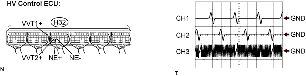
| 8.INSPECT HYBRID VEHICLE CONTROL ECU |
Using an ocilloscope, measure the waveform according to the value(s) in the table below.
| Item | Condition |
| Terminal | CH1: VV1+ - NE- CH2: VV2+ - NE- CH3: NE+ - NE- |
| Equipment Setting | 2 V / DIV, 20 ms / DIV |
| Condition | After engine warmed up and idling |
|
| ||||
| NG | |
| 9.INSPECT CRANKSHAFT POISITOIN SENSOR |
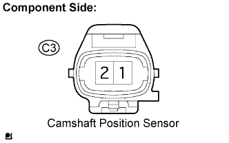 |
Disconnect the C3 connector from the crankshaft position sensor.
Measure the resistance according to the value(s) in the table below.
| Tester Connection | Condition | Specified Condition |
| 1 - 2 | Cold | 1,630 to 2,740 Ω |
| 1 - 2 | Hot | 2,065 to 3,225 Ω |
|
| ||||
| OK | |
| 10.CHECK HARNESS AND CONNECTOR (HV CONTROL ECU - CRANKSHAFT POSITION SENSOR) |
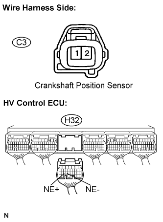 |
Disconnect the H32 connector from the HV control ECU.
Disconnect the C3 connector from the crankshaft position sensor.
| Tester Connection | Specified Condition |
| C3-1 - NE+ (H32-25) | Below 1 Ω |
| C3-2 - NE- (H32-24) | Below 1 Ω |
| Tester Connection | Specified Condition |
| C3-1 or NE+ (H32-25) - Body ground | 10 kΩ or more |
| C3-2 or NE- (H32-24) - Body ground | 10 kΩ or more |
|
| ||||
| OK | |
| 11.CHECK SENSOR INSTALLATION (CRANKSHAFT POSITION SENSOR) |
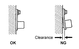 |
Check the crankshaft position sensor installation.
|
| ||||
| OK | |
| 12.CHECK CRANKSHAFT POSITION SENSOR PLATE (TEETH OF SENSOR PLATE) |
Check the teeth of the sensor plate.
|
| ||||
| OK | ||
| ||
