DTC P0A01-725 Motor Electronics Coolant Temperature Sensor Circuit Range / Performance |
DTC P0A01-726 Motor Electronics Coolant Temperature Sensor Circuit Range / Performance |
| DTC No. | INF Code | DTC Detection Condition | Trouble Area |
| P0A01 | 725 | Sudden change in HV coolant temperature sensor output |
|
| ↑ | 726 | HV coolant temperature sensor output deviation |
|
| 1.READ OUTPUT DTC (HV) |
Connect the intelligent tester to the DLC3.
Put the vehicle into the READY-on state and wait for 10 seconds or more.
Select the following menu items: Powertrain / Hybrid Control / DTC.
Read output DTC. (Click here)
| DTC No. | Relevant Diagnosis |
| P0A05-776 | Water pump malfunction |
|
| ||||
| NO | |
| 2.CHECK QUANTITY OF HV COOLANT |
Check the inverter coolant level.
|
| ||||
| OK | |
| 3.CHECK COOLANT HOSE |
 |
Check if the hoses of the cooling system are not bent or clogged.
|
| ||||
| OK | |
| 4.LOOSENESS AND POOR CONTACT |
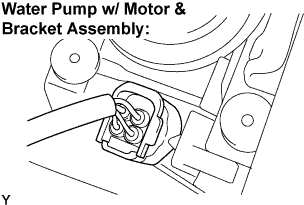 |
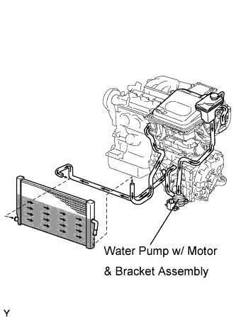
Check the connection of the water pump w/ motor & bracket assembly connector.
|
| ||||
| OK | |
| 5.PERFORM ACTIVE TEST BY INTELLIGENT TESTER (WATER PUMP) |
Connect the intelligent tester to the DLC3.
Turn the ignition switch to the ON position.
Select the following menu items: Powertrain / Hybrid Control / Active Test / Active Water Pump.
During the water pump active test, check operation of the water pump.
|
| ||||
| OK | |
| 6.PERFORM ACTIVE TEST BY INTELLIGENT TESTER (COOLING FAN) |
Connect the intelligent tester to the DLC3.
Turn the ignition switch to the ON position.
Select the following menu items: Powertrain / Engine / Active Test / Cooling Fan.
Perform the cooling fan active test.
|
| ||||
| OK | |
| 7.CHECK CONNECTION CONDITION OF MG ECU CONNECTOR (LOOSENESS AND POOR CONTACT) |
Turn the ignition switch off and remove the service plug grip. (Click here)
Remove the inverter cover. (Click here)
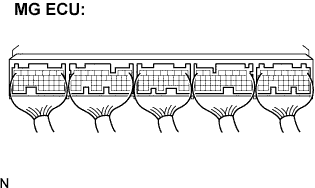 |
Check the connections of all MG ECU connectors.
|
| ||||
| OK | ||
| ||
| 8.CHECK HARNESS AND CONNECTOR (HV CONTROL ECU - WATER PUMP) |
 |
Turn the ignition switch off.
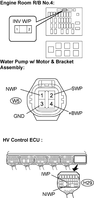
Disconnect the H29 connector from the HV control ECU.
Disconnect the W5 water pump connector.
Measure the resistance according to the value(s) in the table below.
| Tester Connection | Specified Condition |
| NIWP (H29-29) - NWP (W5-1) | Below 1 Ω |
| IWP (H29-23) - SWP (W5-2) | Below 1 Ω |
| GND (W5-3) - Body ground | Below 1 Ω |
| Engine room R/B No.4 INV W/P fuse terminal 2 - +BWP (W5-4) | Below 1 Ω |
| Tester Connection | Specified Condition |
| NIWP (H29-29) or NWP (W5-1) - Body ground | 10 kΩ or more |
| IWP (H29-23) or SWP (W5-2) - Body ground | 10 kΩ or more |
| Engine room R/B No.4 INV W/P fuse terminal 2 or - +BWP (W5-4) - Body ground | 10 kΩ or more |
|
| ||||
| OK | ||
| ||
