DTC P0A08-264 DC / DC Converter Status Circuit |
| DTC No. | INF Code | DTC Detection Condition | Trouble Area |
| P0A08 | 264 | DC/DC converter malfunction |
|
| 1.READ OUTPUT DTC (HV) |
Connect the intelligent tester to the DLC3.
Turn the ignition switch to the ON position.
Select the following menu items: Powertrain / Hybrid Control / DTC.
Read output DTCs. (Click here)
| DTC No. | Relevant Diagnosis |
| P0A94-547, 548, 549 | Boost converter circuit |
| P0AA6-526, 613, 655 | High-voltage insulation problem detection circuit |
| P0AA2-227, P0AA5-229 | SMR circuit |
| P3004-131, 803 | High-voltage system |
| P0A93-346, 347, P0A05-776 | Inverter cooling system |
|
| ||||
| NO | |
| 2.CHECK RELAY BLOCK ASSEMBLY |
Check the installation of the fusible links (DC/DC and MAIN) and fuse (DC/DC-S) in the relay block. Check if the circuits are open.
|
| ||||
| OK | |
| 3.CHECK CONNECTION CONDITION OF HYBRID VEHICLE CONTROL ECU CONNECTOR (LOOSENESS AND POOR CONTACT) |
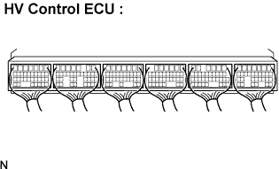 |
Check the connections of all HV control ECU connectors.
|
| ||||
| OK | |
| 4.CHECK CONNECTION CONDITION OF MG ECU CONNECTOR (LOOSENESS AND POOR CONTACT) |
Turn the ignition switch off and remove the service plug grip. (Click here)
Remove the inverter cover. (Click here)
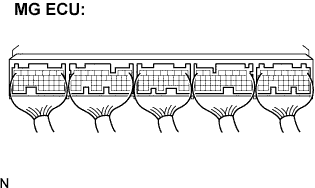 |
Check the connections of the MG ECU connectors.
|
| ||||
| OK | |
| 5.CHECK INSULATION RESISTANCE OF HIGH-VOLTAGE SYSTEM |
Check that the service plug grip is removed.
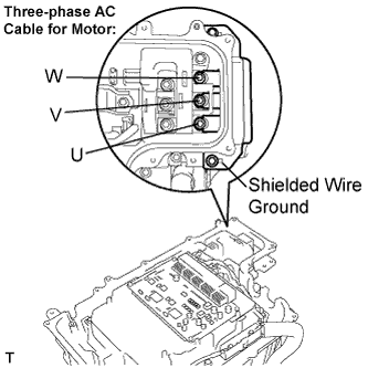 |
Using a megohmmeter, measure the insulation resistance according to the value(s) in the table below.
| Tester Connection | Specified Condition |
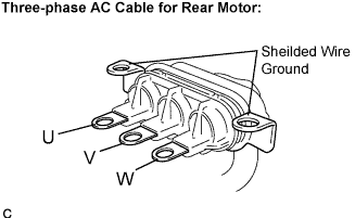
| Three-phase AC Cable for Motor U - Body ground and shielded wire ground | 1 MΩ or higher |
| Three-phase AC Cable for Motor V - Body ground and shielded wire ground | 1 MΩ or higher |
| Three-phase AC Cable for Motor W - Body ground and shielded wire ground | 1 MΩ or higher |
|
| ||||
| OK | |
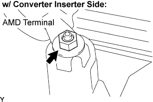
| 6.CHECK CONNECTION OF AMD TERMINAL |
 |
Check that the service plug grip is removed.
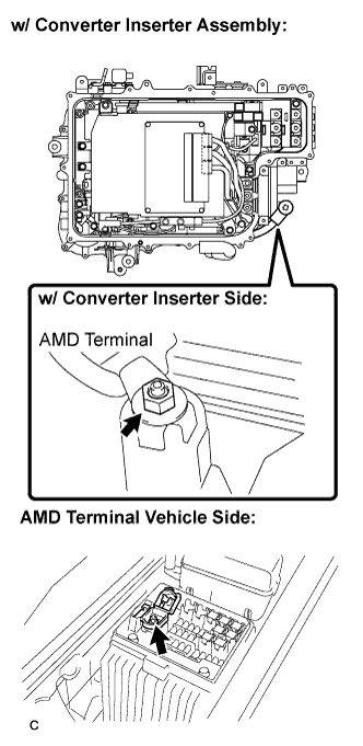 |
Remove the three-phase AC cable for the Rear Motor from the w/ converter inverter assembly.
Check the connection of the AMD terminal.
|
| ||||
| OK | |
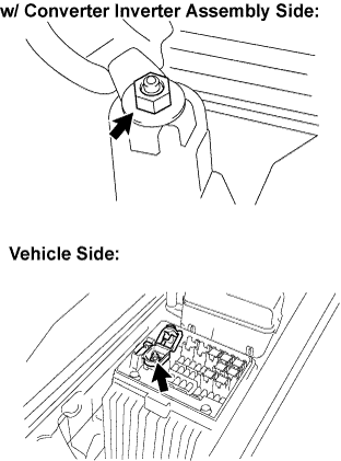
| 7.CHECK AMD TERMINAL VOLTAGE (W/ CONVERTER INVERTER ASSEMBLY SIDE) |
Turn the ignition switch off.
Check that the service plug grip is removed.
 |
Measure the voltage according to the value(s) in the table below.
| Tester Connection | Specified Condition |
| AMD terminal (w/ converter inverter assembly side) - Body ground | 10 to 14 V |
|
| ||||
| OK | |
| 8.INSPECT MG ECU |
Check that the service plug grip is removed.
Turn the ignition switch to the ON position.
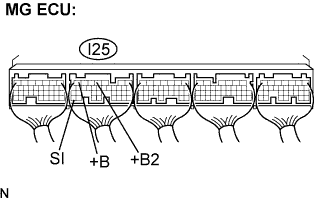 |
Measure the voltage according to the value(s) in the table below.
| Tester Connection | Specified Condition |
| +B (I25-7) - Body ground | 10 to 14 V |
| +B2 (I25-4) - Body ground | 10 to 14 V |
| SI (I25-35) - Body ground | 10 to 14 V |
|
| ||||
| OK | |
| 9.CHECK HARNESS AND CONNECTOR (RESISTANCE VALUE OF NODD INSIDE HV CONTROL ECU) |
Turn the ignition switch off.
Disconnect the I25 connector from the MG ECU.
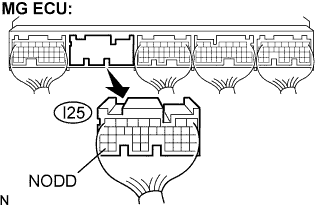 |
Measure the resistance according to the value(s) in the table below.
| Tester Connection | Specified Condition |
| NODD (I25-33) - Body ground | 120 to 140 kΩ |
|
| ||||
| OK | |
| 10.CHECK OPERATION DC/DC CONVERTER |
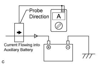 |
Connect the AC/DC 400 A probe to the positive auxiliary battery line.
Install the inverter cover. (Click here)
Install the service plug grip.
Put the vehicle into the READY-on state and leave the vehicle as it is until the electric current flowing into the auxiliary battery becomes 10 A or less.
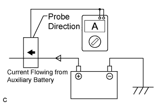 |
Measure the current flowing from the auxiliary battery with the headlight position switch and blower motor switch in the HI position, and the rear window defogger turned on. (*1)
Measure the auxiliary battery voltage according to the previous conditions (*1).
| Measurement Item | Specified Condition |
| Current flowing from auxiliary battery | 0 A or less (no current from auxiliary battery) |
| Auxiliary battery voltage | 13 to 15 V |
|
| ||||
| NG | ||
| ||
| 11.INSPECT HYBRID VEHICLE TRANSAXLE ASSEMBLY (MOTOR AND GENERATOR) |
 |
Check that the service plug grip is removed.
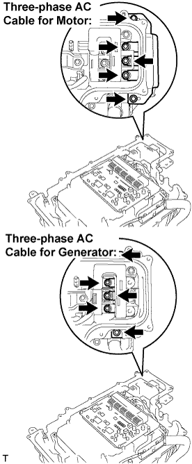
Disconnect the three-phase AC cables of the HV transaxle assembly (Motor and Generator) from the w/ converter inverter assembly.
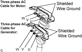 |
Using a megohmmeter, measure the insulation resistance according to the value(s) in the table below.
| Tester Connection | Specified Condition |
| Three-phase AC cable for Motor U terminal - Body ground and shielded wire ground | 10 MΩ or higher |
| Three-phase AC cable for Motor V terminal - Body ground and shielded wire ground | 10 MΩ or higher |
| Three-phase AC cable for Motor W terminal - Body ground and shielded wire ground | 10 MΩ or higher |
| Three-phase AC cable for Generator U terminal - Body ground and shielded wire ground | 10 MΩ or higher |
| Three-phase AC cable for Generator V terminal - Body ground and shielded wire ground | 10 MΩ or higher |
| Three-phase AC cable for Generator W terminal - Body ground and shielded wire ground | 10 MΩ or higher |
|
| ||||
| OK | |
| 12.INSPECT REAR TRACTION MOTOR W/TRANSAXLE ASSEMBLY |
 |
Check that the service plug grip is removed.
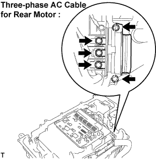
Disconnect the three-phase AC cable for the Rear Motor from the w/ converter inverter assembly.
 |
Using a megohmmeter, measure the insulation resistance according to the value(s) in the table below.
| Tester Connection | Specified Condition |
| Three-phase AC cable for Rear Motor U terminal - Body ground and shielded wire ground | 10 MΩ or higher |
| Three-phase AC cable for Rear Motor V terminal - Body ground and shielded wire ground | 10 MΩ or higher |
| Three-phase AC cable for Rear Motor W terminal - Body ground and shielded wire ground | 10 MΩ or higher |
|
| ||||
| OK | ||
| ||
| 13.CHECK AMD TERMINAL |
 |
Check for ark marks on the AMD terminals (w/ converter inverter assembly side and wire harness side).
|
| ||||
| OK | ||
| ||
| 14.CHECK QUANTITY OF HV COOLANT |
Check the inverter coolant level.
|
| ||||
| OK | |
| 15.CHECK COOLANT HOSE |
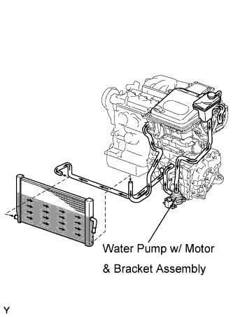 |
Check if the hoses of the cooling system are not bent or clogged.
|
| ||||
| OK | |
| 16.CHECK CONNECTION CONDITION OF WATER PUMP CONNECTOR (LOOSENESS AND POOR CONTACT) |
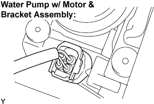 |
Check the connection of the water pump w/ motor & bracket assembly connector.
|
| ||||
| OK | |
| 17.PERFORM ACTIVE TEST BY INTELLIGENT TESTER (WATER PUMP) |
Connect the intelligent tester to the DLC3.
Turn the ignition switch to the ON position.
Select the following menu items: Powertrain / Hybrid Control / Active Test / Active Water Pump.
During the water pump active test, check operation of the water pump.
|
| ||||
| OK | |
| 18.PERFORM ACTIVE TEST BY INTELLIGENT TESTER (COOLING FAN) |
Connect the intelligent tester to the DLC3.
Turn the ignition switch to the ON position.
Select the following menu items: Powertrain / Engine / Active Test / Cooling Fan.
Perform the cooling fan active test.
|
| ||||
| OK | ||
| ||
| 19.CHECK AMD TERMINAL (VEHICLE SIDE) |
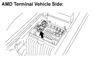 |
Turn the ignition switch off.
Measure the voltage according to the value(s) in the table below.
| Tester Connection | Specified Condition |
| AMD terminal - Body ground | 10 to 14 V |
|
| ||||
| OK | ||
| ||
| 20.INSPECT HYBRID VEHICLE CONTROL ECU |
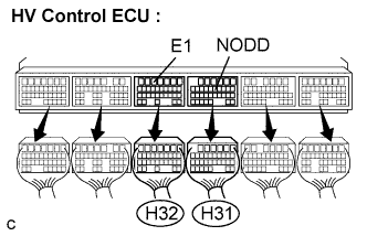 |
Turn the ignition switch off and disconnect all HV control ECU connectors.
Measure the resistance according to the value(s) in the table below.
| Tester Connection | Specified Condition |
| NODD (H31-11) - E1 (H32-5) | 120 to 140 kΩ |
|
| ||||
| OK | ||
| ||
| 21.INSPECT REAR TRACTION MOTOR W/TRANSAXLE ASSEMBLY |
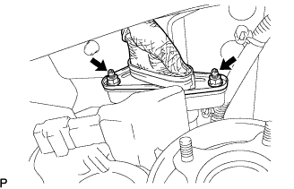 |
Check that the service plug grip is removed.
Disconnect the frame wire No.3 (three-phase AC cable for Rear Motor) from the rear traction motor w/ transaxle assembly.
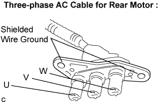 |
Using a megohmmeter, measure the insulation resistance according to the value(s) in the table below.
| Tester Connection | Specified Condition |
| Three-phase AC cable for Rear Motor U terminal - Body ground and shielded wire ground | 10 MΩ or higher |
| Three-phase AC cable for Rear Motor V terminal - Body ground and shielded wire ground | 10 MΩ or higher |
| Three-phase AC cable for Rear Motor W terminal - Body ground and shielded wire ground | 10 MΩ or higher |
|
| ||||
| OK | ||
| ||
