DTC P0A1B-788 Drive Motor "A" Control Module |
| DTC No. | INF Code | DTC Detection Condition | Trouble Area |
| P0A1B | 788 | Error in reset signal from the power source IC |
|
| 1.CHECK CONNECTION CONDITION OF MG ECU CONNECTOR (LOOSENESS AND POOR CONTACT) |
 |
Turn the ignition switch off and remove the service plug grip. (Click here)
Remove the inverter cover. (Click here)
Check the connections of the MG ECU connectors.
|
| ||||
| OK | |
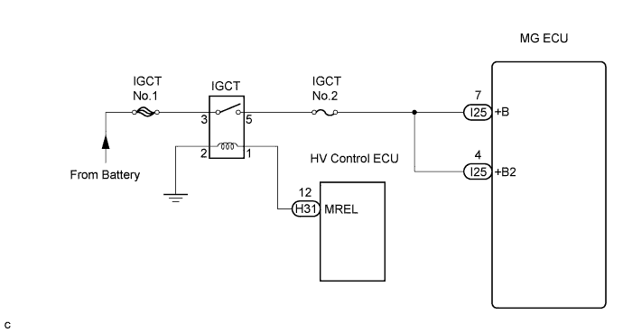
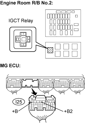
| 2.CHECK HARNESS AND CONNECTOR (IGCT RELAY - MG ECU) |
Check that the service plug grip is removed.
Remove the IGCT relay from the engine room R/B No.2.
Disconnect the I25 connector from the MG ECU.
 |
Measure the resistance according to the value(s) in the table below.
| Tester Connection | Specified Condition |
| +B (I25-7) - Engine room R/B No.2 IGCT relay teminal 5 | Below 1 Ω |
| +B2 (I25-4) - Engine room R/B No.2 IGCT relay teminal 5 | Below 1 Ω |
| Tester Connection | Specified Condition |
| +B (I25-7) or +B2 (I25-4) - Body ground | 10 kΩ or higher |
|
| ||||
| OK | |
| 3.INSPECT MG ECU (+B VOLTAGE) |
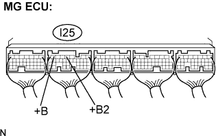 |
Check that the service plug grip is removed.
Measure the voltage according to the value(s) in the table below when the ignition switch is in the ON position.
| Tester Connection | Specified Condition |
| +B (I25-7) - Body ground | 10 V or more |
| +B2 (I25-4) - Body ground | 10 V or more |
|
| ||||
| OK | ||
| ||
