DTC P0A1C-715 Drive Motor "B" Control Module |
DTC P0A1C-798 Drive Motor "B" Control Module |
DTC P0A1C-799 Drive Motor "B" Control Module |
| DTC No. | INF Code | DTC Detection Condition | Trouble Area |
| P0A1C | 715 | R/D resolver angle error |
|
| ↑ | 798 | REF frequency error |
|
| ↑ | 799 | REF signal transmission stop error |
|
| 1.READ OUTPUT DTC (HV) |
Connect the intelligent tester to the DLC3.
Turn the ignition switch to the ON position.
Select the following menu items: Powertrain / Hybrid Control / DTC.
Read output DTC. (Click here)
| DTC No. | Relevant Diagnosis |
| P0A3F-669, P0A46-671, P0A47-670 | Rear Motor resolver circuit |
|
| ||||
| NO | |
| 2.CHECK HARNESS AND CONNECTOR (MG ECU - BODY GROUND) |
Turn the ignition switch off and remove the service plug grip. (Click here)
Remove the inverter cover. (Click here)
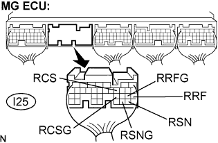 |
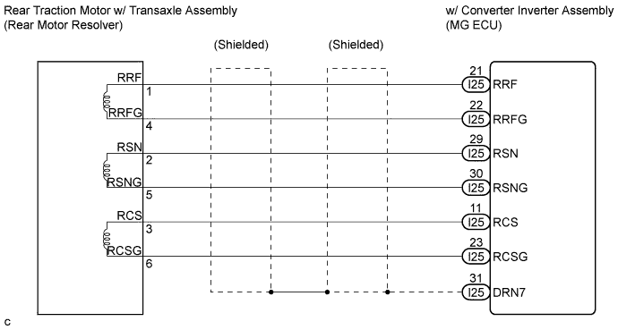
Disconnect the I25 connector from the MG ECU.
Measure the voltage according to the value(s) in the table below when the ignition switch is in the ON position.
| Tester Connection | Specified Condition |
| RRF (I25-21) - Body ground | Below 1 V |
| RRFG (I25-22) - Body ground | Below 1 V |
| RSN (I25-29) - Body ground | Below 1 V |
| RSNG (I25-30) - Body ground | Below 1V |
| RCS (I25-11) - Body ground | Below 1 V |
| RCSG (I25-23) - Body ground | Below 1 V |
Turn the ignition switch off.
Measure the resistance according to the value(s) in the table below.
| Tester Connection | Specified Condition |
| RRF (I25-21) - RRFG (I25-22) | 7.65 to 10.2 Ω |
| RSN (I25-29) - RSNG (I25-30) | 12.6 to 16.8 Ω |
| RCS (I25-11) - RCSG (I25-23) | 12.6 to 16.8 Ω |
Measure the resistance according to the value(s) in the table below.
| Tester Connection | Specified Condition |
| RRF (I25-21) or RRFG (I25-22) - Body ground | 10 kΩ or higher |
| RSN (I25-29) or RSNG (I25-30) - Body ground | 10 kΩ or higher |
| RCS (I25-11) or RCSG (I25-23) - Body ground | 10 kΩ or higher |
|
| ||||
| NG | |
| 3.INSPECT REAR MOTOR RESOLVER |
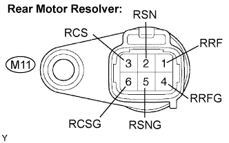 |
Disconnect the M11 rear motor resolver connector.
Measure the resistance according to the value(s) in the table below.
| Tester Connection | Specified Condition |
| RRF (M11-1) - RRFG (M11-4) | 7.65 to 10.2 Ω |
| RSN (M11-2) - RSNG (M11-5) | 12.6 to 16.8 Ω |
| RCS (M11-3) - RCSG (M11-6) | 12.6 to 16.8 Ω |
Using a megohmmeter, measure the insulation resistance according to the value(s) in the table below.
| Tester Connection | Specified Condition |
| RRF (M11-1) - RSN (M11-2) | 10 MΩ or higher |
| RRF (M11-1) - RCS (M11-3) | 10 MΩ or higher |
| RSN (M11-2) - RCS (M11-3) | 10 MΩ or higher |
| RRFG (M11-4) - RSNG (M11-5) | 10 MΩ or higher |
| RRFG (M11-4) - RCSG (M11-6) | 10 MΩ or higher |
| RSNG (M11-5) - RCSG (M11-6) | 10 MΩ or higher |
| Each terminal listed above - Transaxle housing | 10 MΩ or higher |
|
| ||||
| OK | ||
| ||
