DTC P0A38-257 Generator Temperature Sensor Circuit Low |
DTC P0A39-259 Generator Temperature Sensor Circuit High |
| DTC No. | INF Code | DTC Detection Condition | Trouble Area |
| P0A38 | 257 | GND short in generator temperature sensor circuit |
|
| P0A39 | 259 | Open or +B short in generator temperature sensor circuit |
|
| Displayed Temperature | Malfunction |
| -50°C | Open or +B short circuit |
| 205°C | GND short |
| 1.CHECK CONNECTION CONDITION OF HYBRID VEHICLE CONTROL ECU CONNECTOR (LOOSENESS AND POOR CONTACT) |
 |
Check the connections of all HV control ECU connectors.
|
| ||||
| OK | |
| 2.INSPECT HYBRID VEHICLE CONTROL ECU |
 |
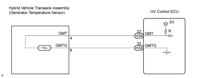
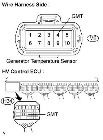
Turn the ignition switch to the ON position. Measure the voltage according to the value(s) in the table below.
| Tester Connection | Voltage | Proceed to |
| GMT (H34-22) - GMTG (H34-32) | Approximately 0 V | A |
| 9 to 14V | B |
|
| ||||
| B | |
| 3.CHECK HARNESS AND CONNECTOR (+B SHORT) |
 |
Disconnect the H34 connector from the HV control ECU.
Turn the ignition switch to the ON position.
Measure the voltage according to the value(s) in the table below.
| Tester Connection | Voltage | Proceed to |
| GMT (H34-22) - GMTG (H34-32) | Approximately 0 V | A |
| 9 to 14V | B |
|
| ||||
| B | |
| 4.CHECK HARNESS AND CONNECTOR (+B SHORT) |
Remove the w/ converter inverter. (Click here)
Disconnect the H34 connector from the HV control ECU.
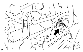 |
Disconnect the M6 generator temperature sensor connector.
Turn the ignition switch to the ON position.
 |
Measure the voltage according to the value(s) in the table below.
| Tester Connection | Specified Condition |
| GMT (M6-4) - Body ground | Approximately 0 V |
|
| ||||
| OK | ||
| ||
| 5.INSPECT GENERATOR TEMPERATURE SENSOR |
|
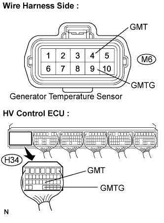
Disconnect the H34 connector from the HV control ECU.
Measure the resistance according to the value(s) in the table below.
| Tester Connection | Resistance | Temperature |
| GMT (H34-22) - GMTG (H34-32) | 142.6 to 184.1 kΩ | 0°C |
| 44.2 to 54.4 kΩ | 25°C | |
| 16.2 to 19.1 kΩ | 50°C | |
| 3.1 to 3.5 kΩ | 100°C |
Measure the resistance according to the value(s) in the table below.
| Tester Connection | Specified Condition |
| GMT (H34-22) or MMTG (H34-32) - Body ground | 10 kΩ or higher |
|
| ||||
| NG | |
| 6.CHECK HARNESS AND CONNECTOR (HV CONTROL ECU - GENERATOR TEMPERATURE SENSOR) |
Remove the w/ converter inverter. (Click here)
Disconnect the H34 connector from the HV control ECU.
Disconnect the M6 generator temperature sensor connector.
 |
Measure the resistance according to the value(s) in the table below.
| Tester Connection | Specified Condition |
| GMT (H34-22) - GMT (M6-4) | Below 1 Ω |
| GMTG (H34-32) - GMTG (M6-9) | Below 1 Ω |
Measure the resistance according to the value(s) in the table below.
| Tester Connection | Specified Condition |
| GMT (H34-22) or GMTG (H34-32) - Body ground | 10 kΩ or higher |
|
| ||||
| OK | ||
| ||
