DTC B1413/13 Evaporator Temperature Sensor Circuit |
| DTC No. | DTC Detecting Condition | Trouble Area |
| B1413/13 | Open or short in evaporator temperature sensor circuit |
|
| 1.READ VALUE OF INTELLIGENT TESTER |
Connect the intelligent tester to the DLC3.
Turn the ignition switch ON and push the intelligent tester main switch on.
Select the item below in the DATA LIST, and read the display on the intelligent tester.
| Item | Measurement Item/Display (Range) | Normal Condition | Diagnostic Note |
| EVAP TEMP | Evaporator temperature sensor / min.: -29.7°C (-21.46°F) max.: 59.55°C (139.19°F) | Actual evaporator temperature is displayed | Open in the circuit: -29.7°C (-21.46°F) Short in the circuit: 59.55°C (139.19°F) |
| Result | Proceed to |
| NG | A |
| OK (Checking from the PROBLEM SYMPTOMS TABLE) | B |
| OK (Checking from the DTC) | C |
|
| ||||
|
| ||||
| A | |
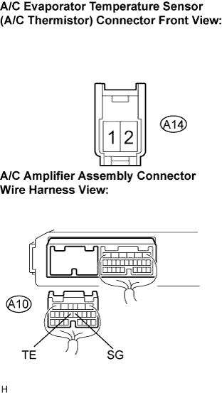
| 2.INSPECT AIR CONDITIONING AMPLIFIER ASSEMBLY |
 |
Remove the A/C amplifier assembly with the connectors still connected.
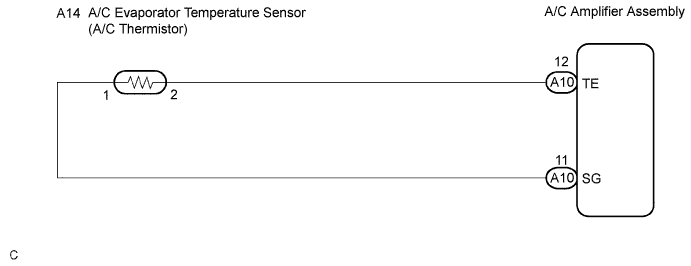
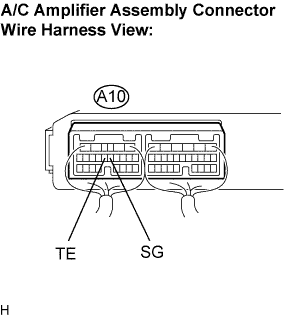
Measure the voltage according to the table value(s) in the table below.
| Tester connection (Symbols) | Condition | Specified condition |
| A10-12 (TE) - A10-11 (SG) | Ignition switch ON at 0°C (32°F) | 2.2 to 2.6 V |
| A10-12 (TE) - A10-11 (SG) | Ignition switch ON at 15°C (59°F) | 1.3 to 1.7 V |
| Result | Proceed to |
| NG | A |
| OK (Checking from the PROBLEM SYMPTOMS TABLE) | B |
| OK (Checking from DTC) | C |
|
| ||||
|
| ||||
| A | |
| 3.INSPECT A/C EVAPORATOR TEMPERATURE SENSOR |
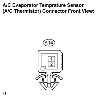 |
Remove the A/C evaporator temperature sensor (A/C thermistor).
Disconnect the connector from the A/C evaporator temperature sensor (A/C thermistor).
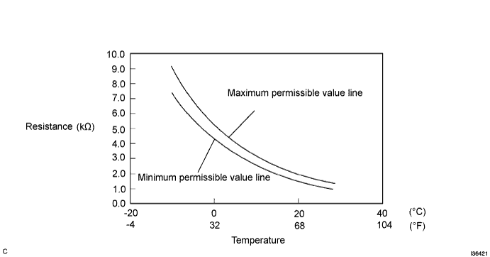
Measure the resistance according to the value(s) in the table below.
| Tester connection | Condition | Specified condition |
| A14-1 - A14-2 | -10°C (14°F) | 7.30 to 9.10 kΩ |
| A14-1 - A14-2 | -5°C (23°F) | 5.65 to 6.95 kΩ |
| A14-1 - A14-2 | 0°C (32°F) | 4.40 to 5.35 kΩ |
| A14-1 - A14-2 | 5°C (41°F) | 3.40 to 4.15 kΩ |
| A14-1 - A14-2 | 10°C (50°F) | 2.70 to 3.25 kΩ |
| A14-1 - A14-2 | 15°C (59°F) | 2.14 to 2.58 kΩ |
| A14-1 - A14-2 | 20°C (68°F) | 1.71 to 2.05 kΩ |
| A14-1 - A14-2 | 25°C (77°F) | 1.38 to 1.64 kΩ |
| A14-1 - A14-2 | 30°C (86°F) | 1.11 to 1.32 kΩ |
|
| ||||
| OK | |
| 4.CHECK HARNESS AND CONNECTOR (A/C EVAPORATOR TEMPERATURE SENSOR - A/C AMPLIFIER ASSEMBLY) |
 |
Disconnect the connector from the A/C amplifier assembly.
Measure the resistance according to the value(s) in the table below.
| Tester connection (Symbols) | Condition | Specified condition |
| A10-12 (TE) - A14-2 | Always | Below 1 Ω |
| A10-11 (SG) - A14-1 | Always | Below 1 Ω |
| A10-12 (TE) - Body ground | Always | 10 kΩ or higher |
| A10-11 (SG) - Body ground | Always | 10 kΩ or higher |
|
| ||||
| OK | ||
| ||
