DTC B1423/23 Pressure Switch Circuit |
| DTC No. | DTC Detecting Condition | Trouble Area |
| B1423/23 |
|
|
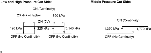
| 1.INSPECT REFRIGERANT PRESSURE |
Set the manifold gauge (Click here).
Read the manifold gauge pressure when the following conditions are established.
|
| ||||
| OK | |
| 2.CHECK AIR CONDITIONING OPERATION |
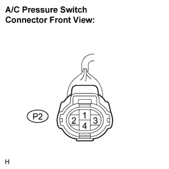 |
Disconnect the connector from the A/C pressure switch.
Connect the terminals 1 and 4 of the connector of the pressure switch on the vehicle wire harness side using a service wire.
Turn the ignition switch ON.
Turn the air conditioning switch ON and check that the compressor is operated.
Check that the compressor is not operated when terminals 1 and 4 are disconnected (that were connected in the prior step).
Check that the electrical fan is operated when terminals 2 and 3 are disconnected (that were connected in the prior step).
|
| ||||
| OK | ||
| ||
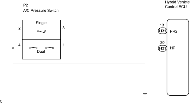
| 3.CHECK HARNESS AND CONNECTOR (A/C PRESSURE SWITCH - HYBRID VEHICLE CONTROL ECU) |
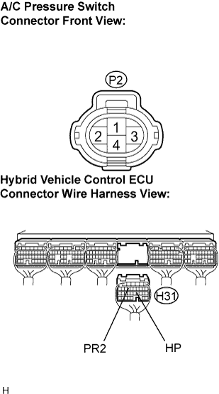 |
Disconnect the connectors from the A/C pressure sensor and the hybrid vehicle control ECU.
Measure the resistance according to the value(s) in the table below.
| Tester connection (Symbols) | Condition | Specified condition |
| H31-13 (PR2) - P2-3 | Always | Below 1 Ω |
| H31-20 (HP) - P2-1 | Always | Below 1 Ω |
| H31-13 (PR2) - Body round | Always | 10 kΩ or higher |
| H31-20 (HP) - Body ground | Always | 10 kΩ or higher |
| P2-2 - Body ground | Always | Below 1 Ω |
| P2-4 - Body ground | Always | Below 1 Ω |
| Result | Proceed to |
| NG | A |
| OK (Checking from the PROBLEM SYMPTOMS TABLE) | B |
| OK (Checking from the DTC) | C |
|
| ||||
|
| ||||
| A | ||
| ||
