DTC B1431/31 Air Mix Damper Position Sensor Circuit (Passenger Side) |
| DTC No. | DTC Detecting Condition | Trouble Area |
| B1431/31 | Open or short in power source circuit in air mix damper position sensor circuit. |
|
| 1.READ VALUE OF INTELLIGENT TESTER |
Connect the intelligent tester to the DLC3.
Turn the ignition switch ON and push the intelligent tester main switch on.
Select the item below in the DATA LIST, and read the display on the intelligent tester.
| Item | Measurement Item/Display (Range) | Normal Condition | Diagnostic Note |
| A/M DAMP POS-P | Air mix damper position (Passenger side) / min.: -14% max.: 113.5% | Damper is at "MAX. COOL": -5% Damper is at "MAX. HOT": 105% | - |
| A/M DAMP TARG-P | Air mix damper target position (Passenger side) / min.: -14% max.: 113.5% |
| Result | Proceed to |
| NG | A |
| OK (Checking from the PROBLEM SYMPTOMS TABLE) | B |
| OK (Checking from the DTC) | C |
|
| ||||
|
| ||||
| A | |
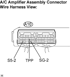
| 2.INSPECT AIR CONDITIONING AMPLIFIER ASSEMBLY |
 |
Remove the A/C amplifier assembly with the connectors still connected.
Change the set temperature to activate the air mix servomotor.
Measure the voltage according to the value(s) in the table below.
| Tester connection (Symbols) | Condition | Specified condition |
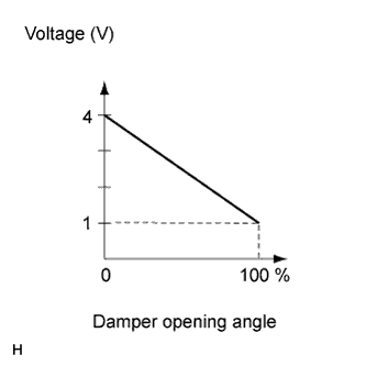
| A10-10 (TPP) - A10-19 (SG-2) | Ignition switch ON MAX.HOT position | 0.82 to 0.88 V |
| A10-10 (TPP) - A10-19 (SG-2) | Ignition switch ON MAX.COOL position | 4.12 to 4.18 V |
| A10-22 (S5-2) - A10-19 (SG-2) | Ignition switch ON | 4.5 to 5.5 V |
| A10-22 (S5-2) - A10-19 (SG-2) | Ignition switch OFF | Below 1 V |
| Result | Proceed to |
| NG | A |
| OK (Checking from the PROBLEM SYMPTOMS TABLE) | B |
| OK (Checking from the DTC) | C |
|
| ||||
|
| ||||
| A | |
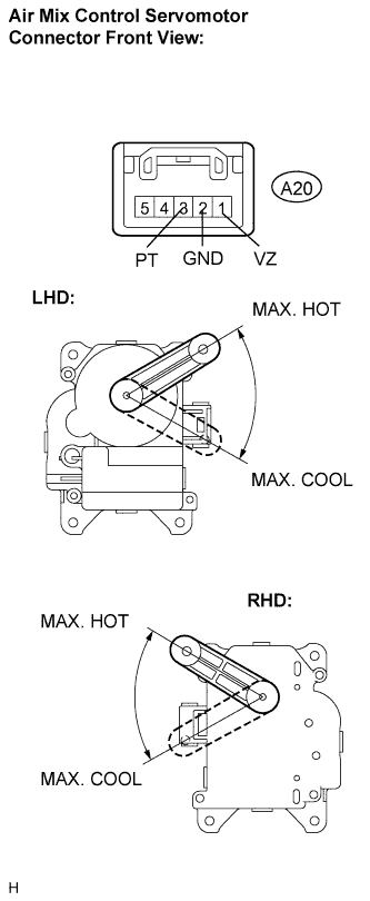
| 3.INSPECT AIR MIX CONTROL SERVOMOTOR |
 |
Remove the air mix control servomotor.
Disconnect the connector from the air mix control servomotor.
Measure the resistance according to the value(s) in the table below.
| Tester connection (Symbols) | Condition | Specified condition |
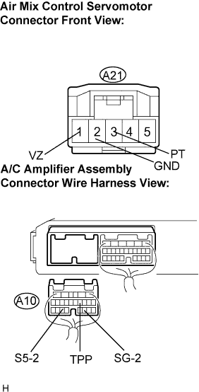
| A21-1 (VZ) - A21-2 (GND) | Always | 4.2 to 7.8 kΩ |
Measure the resistance according to the value(s) in the table below.
| Tester connection | Condition | Specified condition |
| A21-3 (PT) - A21-2 (GND) | MAX. COOL position | 3.5 to 6.5 kΩ |
| A21-3 (PT) - A21-2 (GND) | MAX. HOT position | 0.7 to 1.3 kΩ |
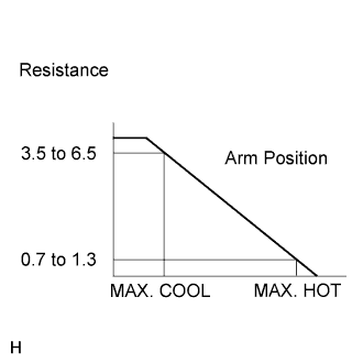 |
As the air mix control servomotor is moved from cool side to hot side, the resistance decreases gradually without interruption.
|
| ||||
| OK | |
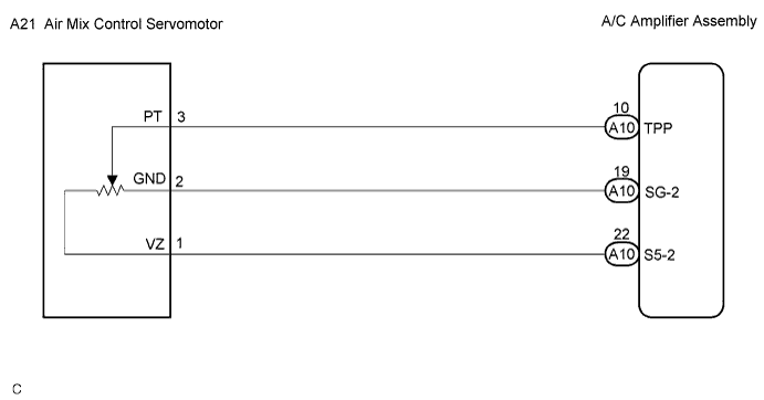
| 4.CHECK HARNESS AND CONNECTOR (AIR MIX CONTROL SERVOMOTOR - A/C AMPLIFIER ASSEMBLY) |
 |
Disconnect the connector from the A/C amplifier assembly.
Measure the resistance according to the value(s) in the table below.
| Tester connection (Symbols) | Condition | Specified condition |
| A10-10 (TPP) - A21-3 (PT) | Always | Below 1 Ω |
| A10-19 (SG-2) - A21-2 (GND) | Always | Below 1 Ω |
| A10-22 (S5-2) - A21-1 (VZ) | Always | Below 1 Ω |
| A10-10 (TPP) - Body ground | Always | 10 kΩ or higher |
| A10-19 (SG-2) - Body ground | Always | 10 kΩ or higher |
| A10-22 (S5-2) - Body ground | Always | 10 kΩ or higher |
|
| ||||
| OK | ||
| ||
