DTC B1446/46 Air Mix Damper Control Servomotor Circuit (Driver Side) |
| DTC No. | DTC Detecting Condition | Trouble Area |
| B1446/46 | Air mix damper position sensor value does not change even if air conditioning amplifier assembly operates air mix servomotor. |
|
| 1.READ VALUE OF INTELLIGENT TESTER |
Connect the intelligent tester to the DLC3.
Turn the ignition switch ON and push the intelligent tester main switch on.
Select the item below in the DATA LIST, and read the display on the intelligent tester.
| Item | Measurement Item/Display (Range) | Normal Condition | Diagnostic Note |
| A/M DAMP POS-D | Air mix damper position (Driver side) / min.: -14% max.: 113.5% | Damper is at "MAX. COOL": -5% Damper is at "MAX. HOT": 105% | - |
| A/M DAMP TARG-D | Air mix damper target position (Driver side) / min.: -14% max.: 113.5% |
| Result | Proceed to |
| NG | A |
| OK (Checking from the PROBLEM SYMPTOM TABLE) | B |
| OK (Checking from the DTC) | C |
|
| ||||
|
| ||||
| A | |
| 2.PERFORM ACTIVE TEST BY INTELLIGENT TESTER |
Connect the intelligent tester to the DLC3.
Turn the ignition switch ON and push the intelligent tester main switch on.
Select the item below in the ACTIVE TEST and then check the air flow temperature by hand.
| Item | Test Details/Display (Range) | Diagnostic Note |
| AIR MIX DAMP-D | Air mix damper (Driver side) /min.: -14% max.: 113.5% | - |
| Result | Proceed to |
| NG | A |
| OK (Checking from the PROBLEM SYMPTOM TABLE) | B |
| OK (Checking from the DTC) | C |
|
| ||||
|
| ||||
| A | |
| 3.PERFORM ACTUATOR CHECK |
Set the actuator check mode (Click here).
Press the DEF switch and change to the step operation.
Check the air flow temperature by hand.
| Display Code | Air Mix Damper Operation |
| 0 | "COOL" side (-5%) |
| 1 | "COOL" side (-5%) |
| 2 | "COOL" side (-5%) |
| 3 | "COOL" side (-5%) |
| 4 | "COOL"/"HOT" (50% opened) |
| 5 | "COOL"/"HOT" (50% opened) |
| 6 | "COOL"/"HOT" (50% opened) |
| 7 | "HOT" side (105%) |
| 8 | "HOT" side (105%) |
| 9 | "HOT" side (105%) |
| Result | Proceed to |
| NG | A |
| OK (Checking from the PROBLEM SYMPTOM TABLE) | B |
| OK (Checking from the DTC) | C |
|
| ||||
|
| ||||
| A | |
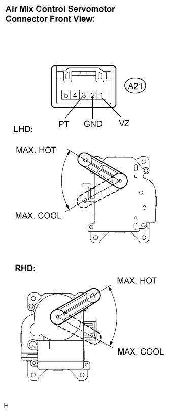
| 4.INSPECT AIR MIX CONTROL SERVOMOTOR |
 |
Remove the air mix control servomotor.
Disconnect the connector from the air mix control servomotor.
Connect the positive (+) lead from the battery to terminal 5 and the negative (-) lead to terminal 4, then check that the lever turns to the "MAX. HOT" position smoothly.
Connect the positive (+) lead from the battery to terminal 4 and the negative (-) lead to terminal 5, then check that the lever turns to the "MAX. COOL" position smoothly.
|
| ||||
| OK | |
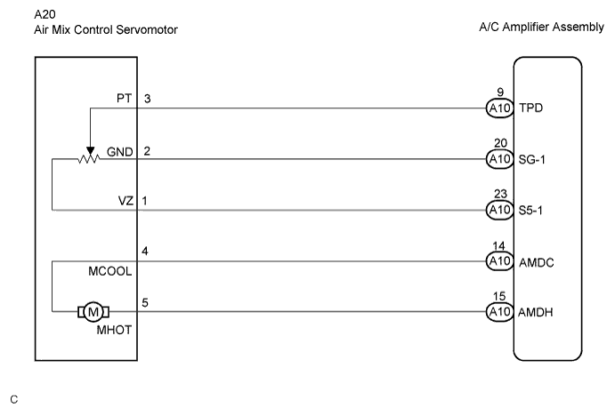
| 5.CHECK HARNESS AND CONNECTOR (AIR MIX CONTROL SERVOMOTOR - A/C AMPLIFIER ASSEMBLY) |
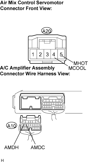 |
Disconnect the connector from the A/C amplifier assembly.
Measure the resistance according to the value(s) in the table below.
| Tester connection (Symbols) | Condition | Specified condition |
| A10-14 (AMDC) - A20-4 (MCOOL) | Always | Below 1 Ω |
| A10-15 (AMDH) - A20-5 (MHOT) | Always | Below 1 Ω |
| A10-14 (AMDC) - Body ground | Always | 10 kΩ or higher |
| A10-15 (AMDH) - Body ground | Always | 10 kΩ or higher |
|
| ||||
| OK | ||
| ||
