AIR CONDITIONING SYSTEM > Blower Motor Circuit |
| 1.READ VALUE OF INTELLIGENT TESTER |
Connect the intelligent tester to the DLC3.
Turn the ignition switch ON and push the intelligent tester main switch on.
Select the item below in the DATA LIST, and read the display on the intelligent tester.
| Item | Measurement Item/Display (Range) | Normal Condition | Diagnostic Note |
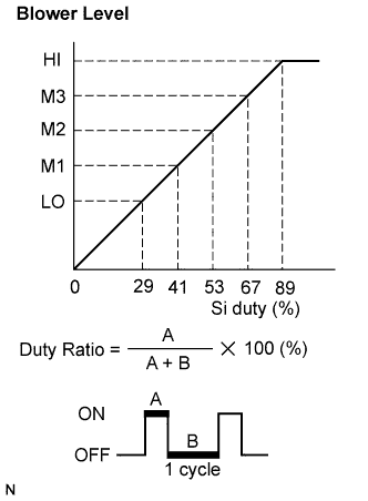
| BLOWER LEVEL | Blower motor speed level /min.: Level 0 max.: Level 31 | Changes depending on blower level | - |
|
| ||||
| OK | ||
| ||
| 2.PERFORM ACTIVE TEST BY INTELLIGENT TESTER |
Connect the intelligent tester to the DLC3.
Turn the ignition switch ON and push the intelligent tester main switch on.
Select the item below in the ACTIVE TEST and then check that the blower motor operates.
| Item | Test Details/Display (Range) | Diagnostic Note |
| BLOWER MOTOR | Blower motor /min.: Level 0 max.: Level 31 | - |
|
| ||||
| OK | ||
| ||
| 3.PERFORM ACTUATOR CHECK |
Set the actuator check mode (Click here).
Press the blower switch to set the step operation.
Check for air flow level by hand.
| Display Code | Blower Level |
| 0 | 0 |
| 1 | 1 |
| 2 | 17 |
| 3 | 17 |
| 4 | 17 |
| 5 | 17 |
| 6 | 17 |
| 7 | 17 |
| 8 | 17 |
| 9 | 31 |
|
| ||||
| OK | ||
| ||
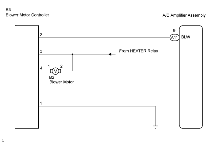
| 4.CHECK HARNESS AND CONNECTOR (BLOWER MOTOR CONTROLLER - A/C AMPLIFIER ASSEMBLY) |
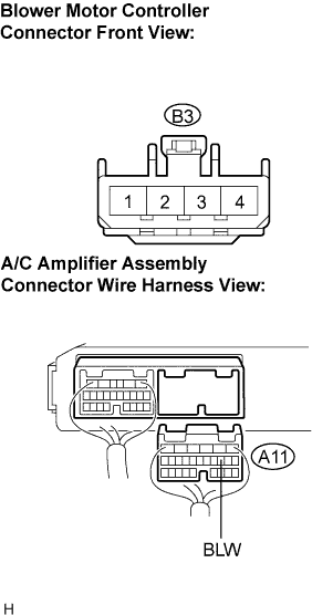 |
Disconnect the connector from the A/C amplifier assembly and the blower motor controller.
Measure the resistance according to the value(s) in the table below.
| Tester connection (Symbols) | Condition | Specified condition |
| A11-9 (BLW) - B3-2 | Always | Below 1 Ω |
| A11-9 (BLW) - Body ground | Always | 10 kΩ or higher |
|
| ||||
| OK | |
| 5.CHECK HARNESS AND CONNECTOR (BLOWER MOTOR CONTROLLER - BODY GROUND) |
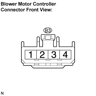 |
Measure the resistance according to the value(s) in the table below.
| Tester connection | Condition | Specified condition |
| B3-1 - Body ground | Always | Below 1 Ω |
|
| ||||
| OK | |
| 6.CHECK HARNESS AND CONNECTOR (BLOWER MOTOR CONTROLLER - BLOWER MOTOR) |
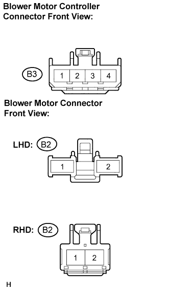 |
Disconnect the connector from the blower motor.
Measure the voltage according to the value(s) in the table below.
| Tester connection | Condition | Specified condition |
| B2-2 - Body ground | Ignition switch ON Blower switch: ON | 10 to 14 V |
| B3-3 - Body ground | Ignition switch ON Blower switch: ON | 10 to 14 V |
| B2-2 - Body ground | Ignition switch ON Blower switch: OFF | Below 1 V |
| B3-3 - Body ground | Ignition switch ON Blower switch: OFF | Below 1 V |
|
| ||||
| OK | |
| 7.CHECK HARNESS AND CONNECTOR (BLOWER MOTOR CONTROLLER - BLOWER MOTOR) |
|
Measure the resistance according to the value(s) in the table below.
| Tester connection | Condition | Specified condition |
| B2-1 - B3-4 | Always | Below 1 Ω |
| B2-1 - Body ground | Always | 10 kΩ or higher |
|
| ||||
| OK | |
| 8.INSPECT COOLING UNIT MOTOR SUB-ASSEMBLY W/FAN |
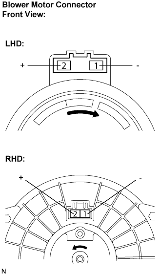 |
Remove the cooling unit motor sub-assembly w/ fan.
Connect the negative (-) lead connected to terminal 1 of the blower motor connector, the positive (+) lead to terminal 2.
|
| ||||
| OK | |
| 9.INSPECT AIR CONDITIONING AMPLIFIER ASSEMBLY |
Reconnect the connector to the A/C amplifier assembly.
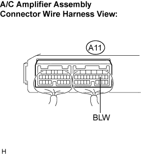 |
Remove the A/C amplifier assembly with the connectors still connected.
Turn the ignition switch to the ON position.
Blower speed switch is at "LO".
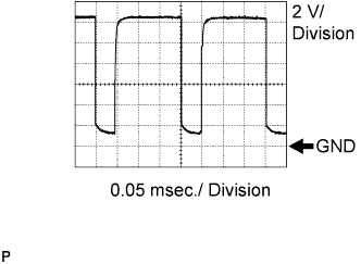 |
Measure the waveform between terminal BLW (A11-9) of the A/C amplifier assembly and body ground.
|
| ||||
| OK | ||
| ||
