DTC B1498/98 Communication Malfunction (A/C Inverter Local) |
| DTC No. | Detection item | Trouble Area |
| B1498/98 |
|
|
| 1.CHECK DIAGNOSTIC TROUBLE CODE |
Check if DTCs for the hybrid control system are output using the intelligent tester.
| Result | Proceed to |
| DTC is not output | A |
| DTC (P3108) is output | A |
| Except DTC (P3108) is output | B |
|
| ||||
| A | |
| 2.INSPECT HEATER FUSE |
Remove the HEATER fuse from instrument panel J/B.
Measure the resistance according to the value(s) in the table below.
| Tester Item | Condition | Specified condition |
| HEATER fuse | Always | Below 1 Ω |
|
| ||||
| OK | |
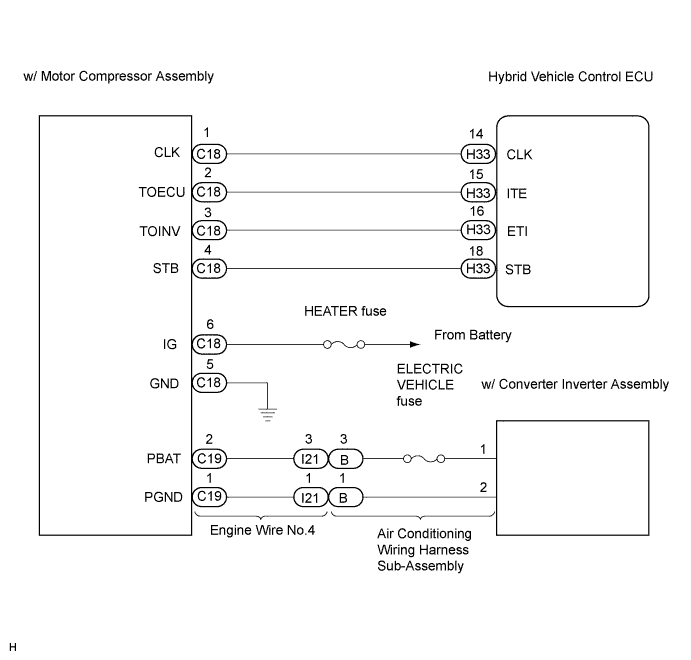
| 3.CHECK HARNESS AND CONNECTOR (W/MOTOR COMPRESSOR ASSEMBLY - BODY GROUND) |
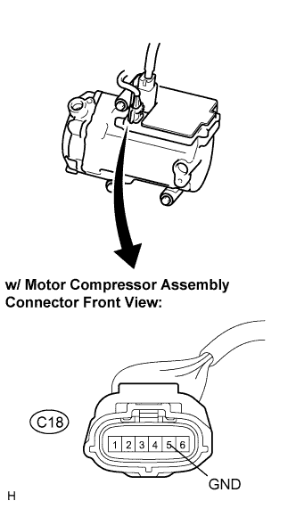 |
Disconnect the connector from the w/ motor compressor assembly.
Measure the resistance according to the value(s) in the table below.
| Tester connection (Symbols) | Condition | Specified condition |
| C18-5 (GND) - Body ground | Always | Below 1 Ω |
|
| ||||
| OK | |
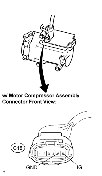
| 4.CHECK HARNESS AND CONNECTOR (IG1 - GND) |
 |
Turn the ignition switch ON.
Measure the voltage according to the value(s) in the table below.
| Tester connection (Symbols) | Condition | Specified condition |
| C18-6 (IG) - C18-5 (GND) | Ignition switch ON | 10 to 14 V |
| C18-6 (IG) - C18-5 (GND) | Ignition switch OFF | Below 1 V |
|
| ||||
| OK | |
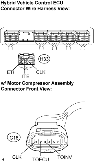
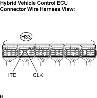
| 5.CHECK HARNESS AND CONNECTOR (HYBRID VEHICLE CONTROL ECU - W/MOTOR COMPRESSOR ASSEMBLY) |
 |
Disconnect the connector from the hybrid vehicle control ECU.
Measure the resistance according to the value(s) in the table below.
| Tester connection (Symbols) | Condition | Specified condition |
| C18-1 (CLK) - H33-14 (CLK) | Always | Below 1 Ω |
| C18-2 (TOECU) - H33-15 (ITE) | Always | Below 1 Ω |
| C18-3 (TOINV) - H33-16 (ETI) | Always | Below 1 Ω |
| C18-1 (CLK) - Body ground | Always | 10 kΩ or higher |
| C18-2 (TOECU) - Body ground | Always | 10 kΩ or higher |
| C18-3 (TOINV) - Body ground | Always | 10 kΩ or higher |
|
| ||||
| OK | |
| 6.INSPECT ELECTRIC VEHICLE FUSE |
Turn the ignition switch off.
Remove the service plug grip.
Remove the inverter cover.
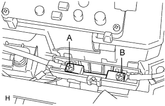 |
Check that the A and B bolts are tightened securely.
Measure the resistance according to the value(s) in the table below.
| Tester Item (Tester connection) | Condition | Specified condition |
| ELECTRIC VEHICLE fuse (A - B) | Always | Below 1 Ω |
|
| ||||
| OK | |
| 7.INSPECT W/CONVERTER INVERTER ASSEMBLY |
Check that the 1 and 2 bolts are tightened securely.
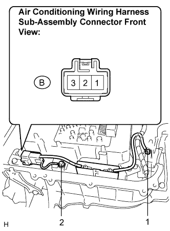 |
Disconnect the connector from the air conditioning wiring harness sub-assembly.
Measure the resistance according to the value(s) in the table below.
| Tester connection | Condition | Specified condition |
| B-3 - 1 | Always | Below 1 Ω |
| B-1 - 2 | Always | Below 1 Ω |
|
| ||||
| OK | |
| 8.INSPECT ENGINE WIRE NO.4 |
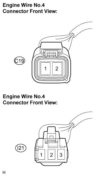 |
Disconnect the connector from the engine wire No.4.
Measure the resistance according to the value(s) in the table below.
| Tester connection (Symbols) | Condition | Specified condition |
| C19-1 (PGND) - I21-1 | Always | Below 1 Ω |
| C19-2 (PBAT) - I21-3 | Always | Below 1 Ω |
| C19-1 (PGND) - C19-2 (PBAT) | Always | 10 kΩ or higher |
|
| ||||
| OK | |
| 9.INSPECT W/MOTOR COMPRESSOR ASSEMBLY |
 |
Reconnect the connectors to the engine wire No.4, the air conditioner harness, the hybrid vehicle control ECU and the w/ motor compressor assembly.
Turn the ignition switch ON.
Measure the waveform according to the condition in the table below.
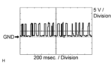 |
CLK - Body ground
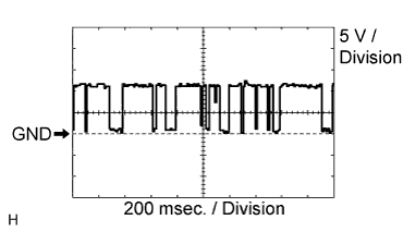 |
ITE - Body ground
|
| ||||
| OK | ||
| ||
