DTC    P0A79-697    Drive Motor "B" Inverter Performance

DTC    P0A79-698    Drive Motor "B" Inverter Performance

for Preparation Click here


DESCRIPTION

Refer to the description of the inverter. (Click here)
If the inverter receives a rear motor gate shutdown signal from the MG ECU, it will turn all power transistors off which are activating the Rear Motor to forcibly stop Motor operation.
The MG ECU monitors the rear motor gate shutdown signal line and detects a malfunction.

DTC No.
INF Code
DTC Detection Condition
Trouble Area
P0A79
697
GND short in rear motor gate shutdown (RSDN) signal line
  1. w/ converter inverter assembly

698
Open or +B short in rear motor gate shutdown (RSDN) signal line
  1. w/ converter inverter assembly

MONITOR DESCRIPTION

The MG ECU monitors the rear motor gate shutdown (RSDN) signal line. If the MG ECU detects an open or short malfunction of the RSDN signal circuit, the HV control ECU illuminates the MIL and sets a DTC.

INSPECTION PROCEDURE

CAUTION:
  1. Before inspecting the high-voltage system, take safety precautions to prevent electrical shocks, such as wearing insulated gloves and removing the service plug grip. After removing the service plug grip, put it in your pocket to prevent other technicians from reconnecting it while you are working on the high-voltage system.
  2. After disconnecting the service plug grip, wait for at least 5 minutes before touching any of the high-voltage connectors or terminals.

HINT:
At least 5 minutes is required to discharge the high-voltage capacitor inside the w/ converter inverter assembly.

1.READ OUTPUT DTC (HV)
  1. Connect the intelligent tester to the DLC3.

  1. Turn the ignition switch to the ON position.

  1. Select the following menu items: Powertrain / Hybrid Control / DTC.

  1. Read output DTC. (Click here)

    Result:
    The DTCs shown in the table below are output:

    DTC No.
    Relevant Diagnosis
    P3232, P3233
    HV gate shutdown wiring malfunction


YES
GO TO DTC CHART
NO


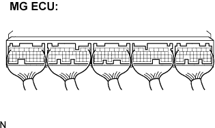
2.CHECK CONNECTION CONDITION OF MG ECU CONNECTOR (LOOSENESS AND POOR CONTACT)

CAUTION:
Be sure to wear insulated gloves.


    A103665E03
  1. Turn the ignition switch off and remove the service plug grip. (Click here)

    NOTICE:
    Do not put the vehicle into the READY-on state with the service plug grip removed as this may cause a malfunction.

  1. Remove the inverter cover. (Click here)

    NOTICE:
    1. Wrap the interlock round terminal for the inverter cover with vinyl tape to prevent it from shorting to ground.
    2. Prevent water in the reservoir tank from entering the inverter.
    3. Removing the inverter cover causes the MG ECU board to be exposed. Therefore, temporarily install the inverter cover for each area to be inspected.

  1. Check the connections of the MG ECU connectors.

    OK:
    Connectors are connected securely and there is no poor connection.


NG
CONNECT SECURELY
OK

REPLACE W/ CONVERTER INVERTER ASSEMBLY