DTC P0A79-704 Drive Motor "B" Inverter Performance |
| DTC No. | INF Code | DTC Detection Condition | Trouble Area |
| P0A79 | 704 | Malfunction in monitoring Rear Motor torque performance |
|
| 1.READ OUTPUT DTC (HV) |
Connect the intelligent tester to the DLC3.
Turn the ignition switch to the ON position.
Select the following menu items: Powertrain / Hybrid Control / DTC.
Read output DTC. (Click here)
| DTC No. | Relevant Diagnosis |
| P0A1A (all details), P0A1B (all details), P0A1C (all details) | MG ECU circuit malfunction |
| P0A1D (all details) | HV ECU circuit malfunction |
| P0A3F-243, P0A40-500, P0A41-245 | Motor resolver circuit malfunction |
| P0A45-669, P0A46-271, P0A47-670 | Rear motor resolver circuit malfunction |
| P0A4B-253, P0A4C-513, P0A4D-255 | Generator resolver circuit malfunction |
| P0A93-147, P0A93-347, P0A05-776 | MG ECU circuit malfunction |
| P0A60 (all details), P0A63 (all details) | Motor current sensor circuit |
| P0A69 (all details), P0A6C (all details) | Rear motor current sensor circuit |
| P0A72 (all details), P0A75 (all details) | Generator current sensor circuit |
| P0A78-510, 508, 586, 266, 272, 280, 304, 267, 278, 283, 285, 305, 523 | Motor inverter function malfunction |
| P0A79-703, 701, 672, 690, 691, 697, 698 | Rear motor inverter function malfunction |
| P0A7A-522, 520, 309, 321, 323, 342, 343 | Generator inverter function malfunction |
| P0A94-585, 587, 561, 551, 588, 589, 545, 546, 552, 558, 559, 583, 584, 590 | Boost converter circuit |
| P0AA6 (all details) | High-voltage system insulation malfunction |
| P3004-132 | High-voltage system |
| P3232-749, P3233-750 | HV gate shutdown wiring malfunction |
|
| ||||
| NO | |
| 2.CHECK REAR TRACTION MOTOR W/TRANSAXLE ASSEMBLY |
 |
Turn the ignition switch off and remove the service plug grip. (Click here)
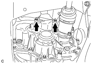
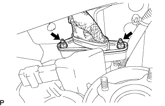
Check that the bolts for the three-phase AC cable of the rear traction motor w/ transaxle assembly are tightened to the specified torque.
|
| ||||
| OK | |
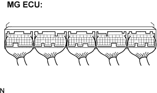
| 3.CHECK CONNECTION CONDITION OF MG ECU CONNECTOR (LOOSENESS AND POOR CONTACT) |
 |
Check that the service plug grip is removed.
Remove the inverter cover. (Click here)
Check the connections of the MG ECU connectors.
|
| ||||
| OK | |
| 4.CHECK W/ CONVERTER INVERTER ASSEMBLY (REAR MOTOR) |
 |
Check that the service plug grip is removed.
Check that the bolts for the three-phase AC cable of the rear traction motor w/ transaxle assembly are tightened to the specified torque.
|
| ||||
| OK | |
| 5.INSPECT REAR TRACTION MOTOR W/TRANSAXLE ASSEMBLY |
 |
Check that the service plug grip is removed.
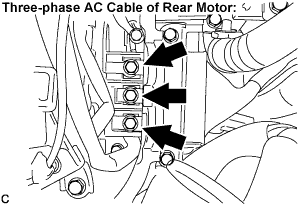
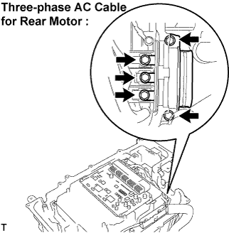
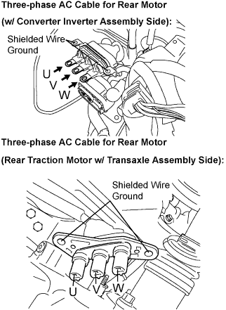
Disconnect the three-phase AC cable for Rear Motor from the inverter.
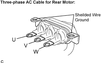 |
Using a milliohmmeter, measure the resistance according to the value(s) in the table below.
| Tester Connection | Specified Condition |
| U - V | 146 to 163 mΩ (20°C) |
| V - W | 146 to 163 mΩ (20°C) |
| W - U | 146 to 163 mΩ (20°C) |
To correct the resistance varying depending on the temperature, use the following formula to calculate the resistance at 20°C.
Calculate the difference between the maximum and minimum resistance.
Using a megohmmeter, measure the insulation resistance according to the value(s) in the table below.
| Tester Connection | Specified Condition |
| U - Body ground and shielded wire ground | 10 MΩ or higher |
| V - Body ground and shielded wire ground | 10 MΩ or higher |
| W - Body ground and shielded wire ground | 10 MΩ or higher |
|
| ||||
| OK | |
| 6.CHECK FRAME WIRE NO.3 (W/ CONVERTER INVERTER ASSEMBLY - REAR TRACTION MOTOR) |
Check that the service plug grip is removed.
 |
Disconnect the three-phase AC cable for Rear Motor from the rear traction motor w/ transaxle assembly.
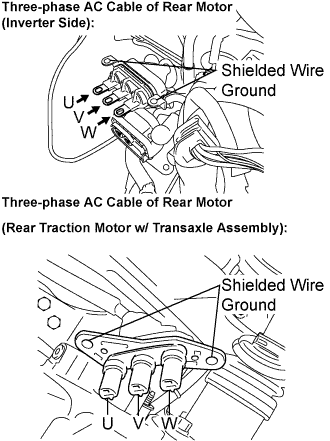 |
Measure the resistance according to the value(s) in the table below.
| Tester Connection (Rear traction motor w/ transaxle assembly side - w/ converter inverter assembly side) | Specified Condition |
| U - U | Below 1 Ω |
| V - V | Below 1 Ω |
| W - W | Below 1 Ω |
|
| ||||
| OK | |
| 7.INSPECT EXTENSION WIRE ASSEMBLY |
Remove the rear traction motor w/ transaxle assembly. (Click here)
Remove the extension wire assembly from the rear traction motor w/ transaxle assembly. (Click here)
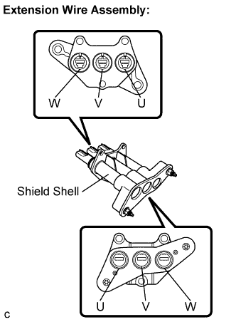 |
Using a megohmmeter, measure the insulation resistance according to the value(s) in the table below.
| Tester Connection | Specified Condition |
| U - Shield shell | 10 MΩ or higher |
| V - Shield shell | 10 MΩ or higher |
| W - Shield shell | 10 MΩ or higher |
Measure the resistance according to the value(s) in the table below.
| Tester Connection | Specified Condition |
| U - U | Below 1 Ω |
| V - V | Below 1 Ω |
| W - W | Below 1 Ω |
|
| ||||
| OK | ||
| ||
| 8.CHECK FRAME WIRE NO.3 (W/ CONVERTER INVERTER ASSEMBLY - REAR TRACTION MOTOR) |
 |
Check that the service plug grip is removed.
Disconnect the three-phase AC cable from the rear motor.
Using a megohmmeter, measure the insulation resistance according to the value(s) in the table below.
| Tester Connection | Specified Condition |
| U - Body ground | 10 MΩ or higher |
| V - Body ground | 10 MΩ or higher |
| W - Body ground | 10 MΩ or higher |
|
| ||||
| OK | |
| 9.INSPECT EXTENSION WIRE ASSEMBLY |
Remove the rear traction motor w/ transaxle assembly. (Click here)
Remove the extension wire assembly from the rear traction motor w/ transaxle assembly. (Click here)
|
Using a megohmmeter, measure the insulation resistance according to the value(s) in the table below.
| Tester Connection | Specified Condition |
| U - Shield shell | 10 MΩ or higher |
| V - Shield shell | 10 MΩ or higher |
| W - Shield shell | 10 MΩ or higher |
Measure the resistance according to the value(s) in the table below.
| Tester Connection | Specified Condition |
| U - U | Below 1 Ω |
| V - V | Below 1 Ω |
| W - W | Below 1 Ω |
|
| ||||
| OK | ||
| ||
