DTC    P3147-239    Transmission Malfunction

DTC    P3147-241    Transmission Malfunction

DTC    P3147-602    Transmission Malfunction

for Preparation Click here


DESCRIPTION

The HV transaxle assembly consists of the planetary gear unit, Motor, and Generator. The gear unit uses the planetary gear to split engine output in accordance with a driving request while the vehicle is driven or the HV battery is charged. The Motor assists engine output while increasing vehicle driving force. The Motor also converts the energy, which is consumed in the form of heat during normal braking, into electrical energy and recover it into the HV battery to effect regenerative braking. The Generator supplies power, which is used for charging the HV battery or driving the Motor. It also controls the stepless transmission function of the transaxle by regulating the amount of electricity generated to change Generator speed. In addition, the Generator is used as a starter Motor to start the engine. The transmission input damper absorbs the shock generated when the driving force from the engine is transmitted.

DTC No.
INF Code
DTC Detection Condition
Trouble Area
P3147
239
HV tansaxle input malfunction (shaft damaged)
  1. Engine
  2. Hybrid vehicle transaxle assembly (shaft, gear)
  3. Transmission input damper
  4. Wire harness or connector
  5. w/ converter inverter assembly (MG ECU)

241
HV transaxle input malfunction (input damper system)
  1. Engine
  2. Hybrid vehicle transaxle assembly (shaft, gear)
  3. Transmission input damper
  4. Wire harness or connector
  5. w/ converter inverter assembly (MG ECU)

602
Transaxle output malfunction
  1. Engine
  2. Hybrid vehicle transaxle assembly (shaft, gear)
  3. Transmission input damper
  4. Wire harness or connector
  5. w/ converter inverter assembly (MG ECU)

INSPECTION PROCEDURE

1.READ OUTPUT DTC (SFI SYSTEM)
  1. Connect the intelligent tester to the DLC3.

  1. Turn the ignition switch to the ON position.

  1. Select the following menu items: Powertrain / Hybrid Control / DTC.

  1. Read output DTC. (Click here)

Result:
DTCs are output.


YES
GO TO DTC CHART
NO


2.CHECK CRANKSHAFT PULLEY REVOLUTION (P POSITION)
  1. Turn the ignition switch off, move the shift lever to the P position, and lift up the vehicle.

  1. Turn the crank pulley by hand to check if the crankshaft rotates.

    CAUTION:
    Do not put the vehicle into the READY-on state while performing this inspection. Be sure to turn the ignition switch off because the engine may start.

    OK:
    The crankshaft rotates.


NG
Go to step 10
OK


3.CHECK HARNESS AND CONNECTOR (HV CONTROL ECU - CRANKSHAFT POSITION SENSOR)


    A105215E02
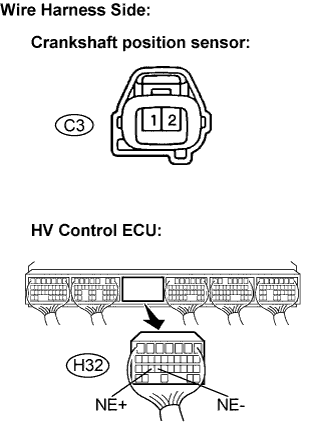
  1. Disconnect the H32connector from the HV control ECU.

  1. Disconnect the C3 crankshaft position sensor connector.

  1. Measure the resistance according to the value(s) in the table below.

    Standard Resistance (Check for open):
    Tester Connection
    Specified Condition
    NE+ (H32-25) - NE+ (C3-1)
    Below 1 Ω
    NE- (H32-24) - NE- (C3-2)
    Below 1 Ω

    Standard Resistance (Check for short):
    Tester Connection
    Specified Condition
    NE+ (H32-25) or NE+ (C3-1) - Body ground
    10 kΩ or higher
    NE- (H32-24) or NE- (C3-2) - Body ground
    10 kΩ or higher

    NOTICE:
    Turning the ignition switch to the ON position with the HV control ECU connectors disconnected causes other DTCs to be stored. Clear the DTCs after performing the inspection.


NG
REPAIR OR REPLACE HARNESS OR CONNECTOR
OK


4.RECONFIRM OUTPUT DTC (HV)
  1. Connect the intelligent tester to the DLC3.

  1. Turn the ignition switch to the ON position.

  1. Select the following menu items: Powertrain / Hybrid Control / DTC.

  1. Check for HV system DTCs, freeze frame data, and diagnosis information and note them down.


NEXT


5.CLEAR DTC
  1. Select the following menu items: Powertrain / Hybrid Control / DTC / Clear.

  1. Clear the DTCs of the HV system.


NEXT


6.CHECK READY LAMP ON
  1. Connect the intelligent tester to the DLC3.

  1. Turn the ignition switch to the ON position.

  1. Select the following menu items: Powertrain / Hybrid Control / Data List / MG1 Rev and Engine Spd.

  1. Put the vehicle into the READY-on state.

    OK:
    The READY light comes on.

    HINT:
    If the READY light does not come on and the reading on the intelligent tester shows DTC P3147-239 (HV transaxle input malfunction [shaft damaged]), or the READY light comes on and the Generator turns but the engine does not crank, replace the HV transaxle assembly.


NG
REPLACE HYBRID VEHICLE TRANSAXLE ASSEMBLY
OK


7.CHECK ENGINE RACING
  1. Connect the intelligent tester to the DLC3.

  1. Turn the ignition switch to the ON position.

  1. Select the following menu items: Powertrain / Hybrid Control / Data List / MG1 Rev and Engine Spd.

  1. While the READY light is on, depress the accelerator pedal for 10 seconds with the shift lever in the P position.

    OK:
    The engine revs up.

    HINT:
    If the engine does not rev up and the reading on the intelligent tester shows DTC P3147-239 (HV transaxle input malfunction [shaft damaged]), or the Generator turns but the engine does not crank, replace the HV transaxle assembly.


NG
REPLACE HYBRID VEHICLE TRANSAXLE ASSEMBLY
OK


8.CHECK CREEP MOVEMENT
  1. Connect the intelligent tester to the DLC3.

  1. Depress the brake pedal, move the shift lever to the D position, and release the brake pedal.

    OK:
    The wheels turn (creeping along).

    HINT:
    If the wheels do not turn and the reading on the intelligent tester shows DTC P3147-602 (HV transaxle output malfunction), replace the HV transaxle assembly.


NG
REPLACE HYBRID VEHICLE TRANSAXLE ASSEMBLY
OK


9.CHECK ENGINE ACCELERATION SPEED
  1. Connect the intelligent tester to the DLC3.

  1. While driving at the vehicle speed of more than 6 mph (10 km/h), fully depress the accelerator pedal to raise the engine speed.

    OK:
    Engine speed increases smoothly.

    HINT:
    If the engine over-revs or the reading on the intelligent tester shows DTC P3147-241 (HV transaxle input malfunction [input damper]), replace the transmission input damper assembly.


NG
REPLACE TRANSMISSION INPUT DAMPER ASSEMBLY
OK

PERFORM SIMULATION TEST. IF SYMPTOM IS NOT REPRODUCED, REPLACE ENGINE, HV TRANSAXLE AND HV CONTROL ECU 

10.CHECK FRONT TIRE REVOLUTION
  1. Turn the ignition switch off and move the shift lever to the N position.

  1. Lift up the vehicle.

  1. Turn the crank pulley by hand to check if the front tires rotate.

    CAUTION:
    Do not put the vehicle into the READY-on state while performing this inspection. Be sure to turn the ignition switch off because the engine may start.

    OK:
    The front tires rotate.


NG
REPAIR OR REPLACE ENGINE
OK

REPLACE HYBRID VEHICLE TRANSAXLE ASSEMBLY