DTC P0A93-346 Inverter Cooling System Performance |
DTC P0A93-347 Inverter Cooling System Performance |
| DTC No. | INF Code | DTC Detection Condition | Trouble Area |
| P0A93 | 346 | Inverter cooling system malfunction (HV coolant malfunction) |
|
| ↑ | 347 | Inverter cooling system malfunction (radiator fan malfunction) |
|
| 1.READ OUTPUT DTC (HV) |
Put the vehicle into the READY-on state and wait for 10 seconds or more.
Connect the intelligent tester to the DLC3.
Turn the ignition switch to the ON position.
Select the following menu items: Powertrain / Hybrid Control / DTC.
Read output DTCs. (Click here)
| DTC No. | Relevant Diagnosis |
| P0A05-776 | Water pump malfunction |
|
| ||||
| NO | |
| 2.CHECK QUANTITY OF HV COOLANT |
Check the inverter coolant level.
|
| ||||
| OK | |
| 3.CHECK COOLANT HOSE |
 |
Check if the hoses of the cooling system are not bent or clogged.
|
| ||||
| OK | |
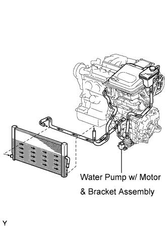
| 4.CHECK CONNECTION CONDITION OF WATER PUMP CONNECTOR (LOOSENESS AND POOR CONTACT) |
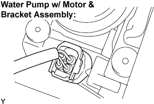 |
Check the connection of the water pump w/ motor connector.
|
| ||||
| OK | |
| 5.PERFORM ACTIVE TEST BY INTELLIGENT TESTER (WATER PUMP) |
Connect the intelligent tester to the DLC3.
Turn the ignition switch to the ON position.
Select the following menu items: Powertrain / Hybrid Control / Active Test / Active Water Pump.
During the water pump active test, check operation of the water pump.
|
| ||||
| OK | |
| 6.CHECK CONNECTION CONDITION OF COOLING FAN CONNECTOR (LOOSENESS AND POOR CONTACT) |
Check the connection of the electric cooling fan connector.
|
| ||||
| OK | |
| 7.PERFORM ACTIVE TEST BY INTELLIGENT TESTER (COOLING FAN) |
Connect the intelligent tester to the DLC3.
Turn the ignition switch to the ON position.
Select the following menu items: Powertrain / Engine / Active Test / Cooling Fan.
During the cooling fan activate test, check operation of the electric cooling fan.
|
| ||||
| OK | ||
| ||
| 8.CHECK HARNESS AND CONNECTOR (HV CONTROL ECU - WATER PUMP) |
Turn the ignition switch off.
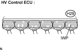
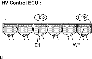
Disconnect the H29 connector from the HV control ECU.
Disconnect the W5 water pump connector.
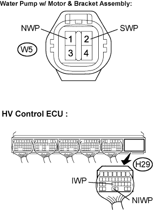 |
Measure the resistance according to the value(s) in the table below.
| Tester Connection | Specified Condition |
| NIWP (H29-29) - NWP (W5-1) | Below 1 Ω |
| IWP (H29-23) - SWP (W5-2) | Below 1 Ω |
| Tester Connection | Specified Condition |
| NIWP (H29-29) or NWP (W5-1)- Body ground | 10 kΩ or higher |
| IWP (H29-23) or SWP (W5-2)- Body ground | 10 kΩ or higher |
|
| ||||
| OK | |
| 9.CHECK HARNESS AND CONNECTOR (WATER PUMP - INV W/P FUSE, WATER PUMP - BODY GROUND) |
Turn the ignition switch off.
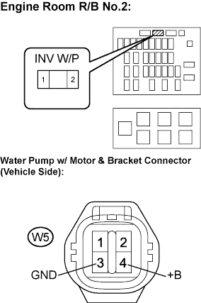 |
Measure the resistance according to the value(s) in the table below.
| Tester Connection | Specified Condition |
| +B (W5-4) - Engine Room R/B No.4 INV W/P fuse terminal 2 | Below 1 Ω |
| GND (W5-3) - Body ground | Below 1 Ω |
| Tester Connection | Specified Condition |
| +B (W5-4) or Engine Room R/B No.4 INV W/P fuse terminal 2 - Body ground | 10 kΩ or higher |
|
| ||||
| OK | |
| 10.CHECK HYBRID VEHICLE CONTROL ECU |
Connect the HV control ECU connector.
Put the vehicle into the READY-on state.
 |
Measure the voltage according to the value(s) in the table below.
| Tester Connection | Specified Condition |
| IWP (H29-23) - Body ground | Below 1 V |
|
| ||||
| NG | |
| 11.INSPECT WATER PUMP W/ MOTOR & BRACKET ASSEMBLY |
 |
Disconnect the H29 HV control ECU Connector.
Turn the ignition switch to the ON position.
Measure the voltage according to the value(s) in the table below.
| Tester Connection | Specified Condition |
| IWP (H29-23) - E1 (H32-5) | 10 to 14 V |
|
| ||||
| OK | ||
| ||
| 12.INSPECT HYBRID VEHICLE CONTROL ECU |
Connect the HV control ECU connector.
Put the vehicle into the READY-on state.
 |
Measure the voltage according to the value(s) in the table below.
| Tester Connection | Specified Condition |
| IWP (H29-23) - E7 (H32-5) | 10 to 14 V |
|
| ||||
| OK | ||
| ||
