DTC P0A94-547 DC / DC Converter Performance |
DTC P0A94-548 DC / DC Converter Performance |
| DTC No. | INF Code | DTC Detection Condition | Trouble Area |
| P0A94 | 547 | Boost converter overvoltage signal detection (overvoltage by MG ECU malfunction) |
|
| ↑ | 548 | Boost converter overvoltage signal detection (overvoltage by inverter malfunction) |
|
| 1.READ OUTPUT DTC (HV) |
Connect the intelligent tester to the DLC3.
Turn the ignition switch to the ON position.
Select the following menu items: Powertrain / Hybrid Control / DTC.
Read output DTCs. (Click here)
| DTC No. | INF Code | Detection Item |
| P0A78 | 266, 280 | Motor inverter function malfunction |
| P0A94 | 558, 559, 588, 589 | Boost converter circuit malfunction |
| P0A95 | 123 | High voltage fuse blown out |
| P0AA1 | 226 | SMR+ stuck closed |
| P0AA2 | 227 | SMR+ stuck open |
| P0AA4 | 228 | SMR- stuck closed |
| P0AA5 | 229 | SMR- stuck open |
| P3004 | 803 | High-current wiring malfunction |
|
| ||||
| NO | |
| 2.CHECK CONNECTION CONDITION OF MG ECU CONNECTOR (LOOSENESS AND POOR CONTACT) |
Turn the ignition switch off and remove the service plug grip. (Click here)
Remove the inverter cover. (Click here)
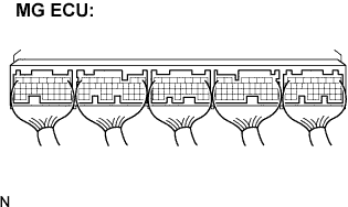 |
Check the connections of all MG ECU connectors.
|
| ||||
| OK | |
| 3.INSPECT HV RELAY ASSEMBLY (SMR2) |
Check that the service plug grip is removed.
Remove the HV relay assembly from the vehicle.
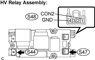 |
Measure the resistance according to the value(s) in the table below.
| Tester Connection | Specified Condition |
| S47-1 - S44-1 | Below 1 Ω (Apply auxiliary battery voltage between terminals CON2 (S48-1) and GND (S48-4)) |
Measure the resistance according to the value(s) in the table below.
| Tester Connection | Specified Condition |
| CON2 (S48-1) - GND (S48-4) | 20 to 60 Ω at -35 to 80°C ( -31 to 176°F) |
|
| ||||
| OK | |
| 4.INSPECT HV RELAY ASSEMBLY (SMR3) |
Check that the service plug grip is removed.
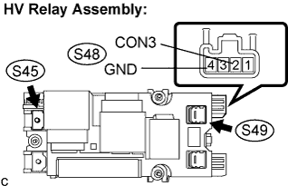 |
Measure the resistance according to the value(s) in the table below.
| Tester Connection | Specified Condition |
| S49-1 - S45-1 | Below 1 Ω (Apply auxiliary battery voltage between terminals CON3 (S48-2) and GND (S48-4)) |
Measure the resistance according to the value(s) in the table below.
| Tester Connection | Specified Condition |
| CON3 (S48-2) - GND (S48-4) | 20 to 60 Ω at -35 to 80°C ( -31 to 176°F) |
|
| ||||
| OK | ||
| ||
