DTC P0A94-553 DC / DC Converter Performance |
| DTC No. | INF Code | DTC Detection Condition | Trouble Area |
| P0A94 | 553 | Boost converter fail (FCV) signal detection (boost converter overheating) |
|
| 1.READ OUTPUT DTC (HV) |
Connect the intelligent tester to the DLC3.
Turn the ignition switch to the ON position.
Select the following menu items: Powertrain / Hybrid Control / DTC.
Read output DTCs. (Click here)
| DTC No. | Relevant Diagnosis |
| P0A1D | HV ECU circuit malfunction |
| P0A2B, P0A2C, P0A2D | Motor temperature sensor circuit |
| P0A37, P0A38, P0A39 | Generator temperature sensor circuit |
| P0A3F, P0A40, P0A41 | Motor resolver circuit |
| P0A4B, P0A4C, P0A4D | Generator resolver circuit |
| P0A60, P0A63 | Motor current sensor circuit |
| P0A72, P0A75 | Generator current sensor circuit |
| P0A78 | Motor inverter function malfunction |
| P0A7A | Generator inverter function malfunction |
| P0A90 | Motor function malfunction |
| P0A92 | Generator function malfunction |
| P0A93 | Inverter cooling system |
| P0A94 (Except for 553) | Boost converter function malfunction |
| P0AA1, P0AA2, P0AA4, P0AA5 | System main relay circuit |
| P0AA6, P3004 | High-voltage system |
| P3211 | Motor inverter temperature sensor circuit |
| P0AEE, P0AEF, P0AF0 | Generator inverter temperature sensor circuit |
| P3226 | Boost converter temperature sensor circuit |
| P0A05 | Water pump w/ motor malfunction |
| P0A79 | Rear motor inverter function malfunction |
| P0AF3, P0AF4, P0AF5 | Rear motor temperature sensor malfunction |
| P0A45, P0A46, P0A47 | Rear motor resolver malfunction |
| P0A69, P0A6C, P0A55 | Rear motor current sensor malfunction |
|
| ||||
| NO | |
| 2.CHECK QUANTITY OF HV COOLANT |
Check the inverter coolant level.
|
| ||||
| OK | |
| 3.CHECK COOLANT HOSE |
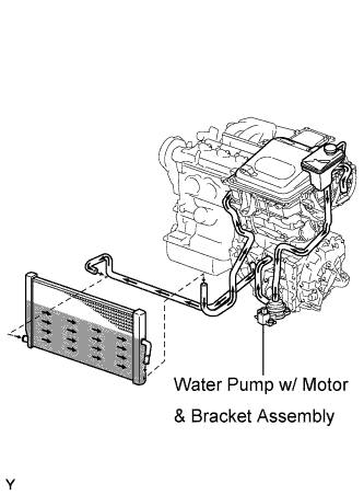 |
Check if the hoses of the cooling system are not bent or clogged.
|
| ||||
| OK | |
| 4.LOOSENESS AND POOR CONTACT |
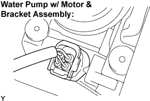 |
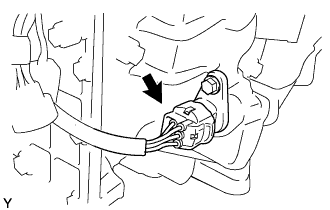
Check the connection of the water pump w/ motor connector.
|
| ||||
| OK | |
| 5.PERFORM ACTIVE TEST BY INTELLIGENT TESTER (WATER PUMP) |
Connect the intelligent tester to the DLC3.
Turn the ignition switch to the ON position.
Select the following menu items: Powertrain / Hybrid Control / Active Test / Active Water Pump.
During the water pump active test, check operation of the water pump.
|
| ||||
| OK | |
| 6.PERFORM ACTIVE TEST BY INTELLIGENT TESTER (COOLING FAN) |
Connect the intelligent tester to the DLC3.
Turn the ignition switch to the ON position.
Select the following menu items: Powertrain / Engine / Active Test / Cooling Fan.
Perform the cooling fan active test.
|
| ||||
| OK | |
| 7.CHECK CONNECTION CONDITION OF HYBRID VEHICLE CONTROL ECU CONNECTOR (LOOSENESS AND POOR CONTACT) |
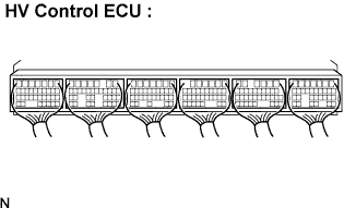 |
Check the connections of all HV control ECU connectors.
|
| ||||
| OK | |
| 8.CHECK CONNECTION CONDITION OF MG ECU CONNECTOR (LOOSENESS AND POOR CONTACT) |
Turn the ignition switch off and remove the service plug grip. (Click here)
Remove the inverter cover. (Click here)
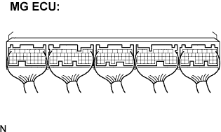 |
Check the connections of the MG ECU connectors.
|
| ||||
| OK | |
| 9.CHECK HARNESS AND CONNECTOR (MG ECU - MOTOR RESOLVER) |
Check that the service plug grip is removed.
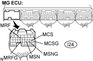 |
Disconnect the I24 connector from the MG ECU.
Measure the voltage according to the value(s) in the table below when the ignition switch is in the ON position.
| Tester Connection | Specified Condition |
| MRF (I24-13) - Body ground | Below 1 V |
| MRFG (I24-23) - Body ground | Below 1 V |
| MSN (I24-21) - Body ground | Below 1 V |
| MSNG (I24-20) - Body ground | Below 1V |
| MCS (I24-19) - Body ground | Below 1 V |
| MCSG (I24-18) - Body ground | Below 1 V |
Turn the ignition switch off.
Measure the resistance according to the value(s) in the table below.
| Tester Connection | Specified Condition |
| MRF (I24-13) - MRFG (I24-23) | 7.65 to 10.2 Ω |
| MSN (I24-21) - MSNG (I24-20) | 12.6 to 16.8 Ω |
| MCS (I24-19) - MCSG (I24-18) | 12.6 to 16.8 Ω |
Measure the resistance according to the value(s) in the table below.
| Tester Connection | Specified Condition |
| MRF (I24-13) or MRFG (I24-23) - Body ground | 10 kΩ or higher |
| MSN (I24-21) or MSNG (I24-20) - Body ground | 10 kΩ or higher |
| MCS (I24-19) or MCSG (I24-18) - Body ground | 10 kΩ or higher |
|
| ||||
| OK | |
| 10.CHECK HARNESS AND CONNECTOR (MG ECU - GENERATOR RESOLVER) |
Check that the service plug grip is removed.
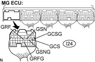 |
Disconnect the I24 connector from the MG ECU.
Measure the voltage according to the value(s) in the table below when the ignition switch is in the ON position.
| Tester Connection | Specified Condition |
| GRF (I24-12) - Body ground | Below 1 V |
| GRFG (I24-22) - Body ground | Below 1 V |
| GSN (I24-11) - Body ground | Below 1 V |
| GSNG (I24-10) - Body ground | Below 1 V |
| GCS (I24-9) - Body ground | Below 1 V |
| GCSG (I24-8) - Body ground | Below 1 V |
Turn the ignition switch off.
Measure the resistance according to the value(s) in the table below.
| Tester Connection | Specified Condition |
| GRF (I24-12) - GRFG (I24-22) | 7.65 to 10.2 Ω |
| GSN (I24-11) - GSNG (I24-10) | 12.6 to 16.8 Ω |
| GCS (I24-9) - GCSG (I24-8) | 12.6 to 16.8 Ω |
Measure the resistance according to the value(s) in the table below.
| Tester Connection | Specified Condition |
| GRF (I24-12) or GRFG (I24-22) - Body ground | 10 kΩ or higher |
| GSN (I24-11) or GSNG (I24-10) - Body ground | 10 kΩ or higher |
| GCS (I24-9) or GCSG (I24-8) - Body ground | 10 kΩ or higher |
|
| ||||
| OK | |
| 11.CHECK HARNESS AND CONNECTOR (MG ECU - REAR MOTOR RESOLVER) |
Check that the service plug grip is removed.
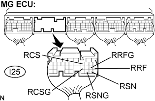 |
Disconnect the I25 connector from the MG ECU.
Measure the voltage according to the value(s) in the table below when the ignition switch is in the ON position.
| Tester Connection | Specified Condition |
| RRF (I25-21) - Body ground | Below 1 V |
| RRFG (I25-22) - Body ground | Below 1 V |
| RSN (I25-29) - Body ground | Below 1 V |
| RSNG (I25-30) - Body ground | Below 1 V |
| RCS (I25-11) - Body ground | Below 1 V |
| RCSG (I25-23) - Body ground | Below 1 V |
Turn the ignition switch off.
Measure the resistance according to the value(s) in the table below.
| Tester Connection | Specified Condition |
| RRF (I25-21) - RRFG (I25-22) | 7.65 to 10.2 Ω |
| RSN (I25-29) - RSNG (I25-30) | 12.6 to 16.8 Ω |
| RCS (I25-11) - RCSG (I25-23) | 12.6 to 16.8 Ω |
Measure the resistance according to the value(s) in the table below.
| Tester Connection | Specified Condition |
| RRF (I25-21) or RRFG (I25-22) - Body ground | 10 kΩ or higher |
| RSN (I25-29) or RSNG (I25-30) - Body ground | 10 kΩ or higher |
| RCS (I25-11) or RCSG (I25-23) - Body ground | 10 kΩ or higher |
|
| ||||
| OK | ||
| ||
| 12.INSPECT MOTOR RESOLVER |
 |
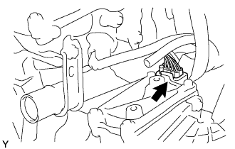
Disconnect the M7 motor resolver connector.
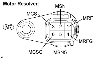 |
Measure the resistance according to the value(s) in the table below.
| Tester Connection | Specified Condition |
| MRF (M7-1) - MRFG (M7-4) | 7.65 to 10.2 Ω |
| MSN (M7-2) - MSNG (M7-5) | 12.6 to 16.8 Ω |
| MCS (M7-3) - MCSG (M7-6) | 12.6 to 16.8 Ω |
Using a megohmmeter, measure the insulation resistance according to the value(s) in the table below.
| Tester Connection | Specified Condition |
| MRF (M7-1) - MSN (M7-2) | 10 MΩ or higher |
| MRF (M7-1) - MCS (M7-3) | 10 MΩ or higher |
| MSN (M7-2) - MCS (M7-3) | 10 MΩ or higher |
| MRFG (M7-4) - MSNG (M7-5) | 10 MΩ or higher |
| MRFG (M7-4) - MCSG (M7-6) | 10 MΩ or higher |
| MSNG (M7-5) - MCSG (M7-6) | 10 MΩ or higher |
| Each terminal listed above - Transaxle housing | 10 MΩ or higher |
|
| ||||
| OK | ||
| ||
| 13.INSPECT GENERATOR RESOLVER |
Remove the w/ converter inverter assembly. (Click here)
 |
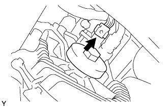
Disconnect the M6 generator resolver connector.
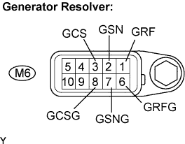 |
Measure the resistance according to the value(s) in the table below.
| Tester Connection | Specified Condition |
| GRF (M6-1) - GRFG (M6-6) | 7.65 to 10.2 Ω |
| GSN (M6-2) - GSNG (M6-7) | 12.6 to 16.8 Ω |
| GCS (M6-3) - GCSG (M6-8) | 12.6 to 16.8 Ω |
Using a megohmmeter, measure the insulation resistance according to the value(s) in the table below.
| Tester Connection | Specified Condition |
| GRF (M6-1) - GSN (M6-2) | 10 MΩ or higher |
| GRF (M6-1) - GCS (M6-3) | 10 MΩ or higher |
| GSN (M6-2) - GCS (M6-3) | 10 MΩ or higher |
| GRFG (M6-6) - GSNG (M6-7) | 10 MΩ or higher |
| GRFG (M6-6) - GCSG (M6-8) | 10 MΩ or higher |
| GSNG (M6-7) - GCSG (M6-8) | 10 MΩ or higher |
| Each terminal listed above - Transaxle housing | 10 MΩ or higher |
|
| ||||
| OK | ||
| ||
| 14.INSPECT REAR MOTOR RESOLVER |
 |
Disconnect the M11 rear motor resolver connector.
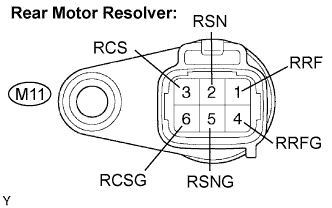 |
Measure the resistance according to the value(s) in the table below.
| Tester Connection | Specified Condition |
| RRF (M11-1) - RRFG (M11-4) | 7.65 to 10.2 Ω |
| RSN (M11-2) - RSNG (M11-5) | 12.6 to 16.8 Ω |
| RCS (M11-3) - RCSG (M11-6) | 12.6 to 16.8 Ω |
Using a megohmmeter, measure the insulation resistance according to the value(s) in the table below.
| Tester Connection | Specified Condition |
| RRF (M11-1) - RSN (M11-2) | 10 MΩ or higher |
| RRF (M11-1) - RCS (M11-3) | 10 MΩ or higher |
| RSN (M11-2) - RCS (M11-3) | 10 MΩ or higher |
| RRFG (M11-4) - RSNG (M11-5) | 10 MΩ or higher |
| RRFG (M11-4) - RCSG (M11-6) | 10 MΩ or higher |
| RSNG (M11-5) - RCSG (M11-6) | 10 MΩ or higher |
| Each terminal listed above - Transaxle housing | 10 MΩ or higher |
|
| ||||
| OK | ||
| ||
