DTC P0A94-583 DC / DC Converter Performance |
DTC P0A94-584 DC / DC Converter Performance |
| DTC No. | INF Code | DTC Detection Condition | Trouble Area |
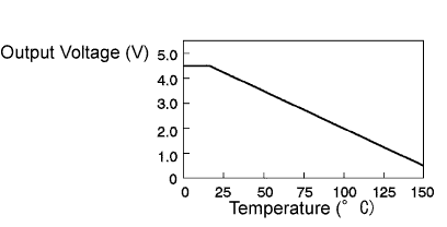
| P0A94 | 583 | Open or GND short in boost converter temperature sensor circuit |
|
| ↑ | 584 | +B short in boost converter temperature sensor circuit |
|
| 1.CHECK CONNECTION CONDITION OF MG ECU CONNECTOR (LOOSENESS AND POOR CONTACT) |
Turn the ignition switch off and remove the service plug grip. (Click here)
Remove the inverter cover. (Click here)
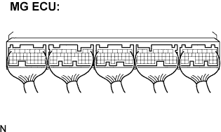 |
Check the connections of the MG ECU connectors.
|
| ||||
| OK | ||
| ||
